D2 Series Servo Drive User Manual LCD Operation
HIWIN MIKROSYSTEM CORP. 7-11
Note:
(1) Only for the drive supporting the single-turn absolute encoder.
(2) Only for the drive supporting the dual-loop encoder.
(3) Only for D2T model.
(4) Only for the drive supporting the 13-bit encoder.
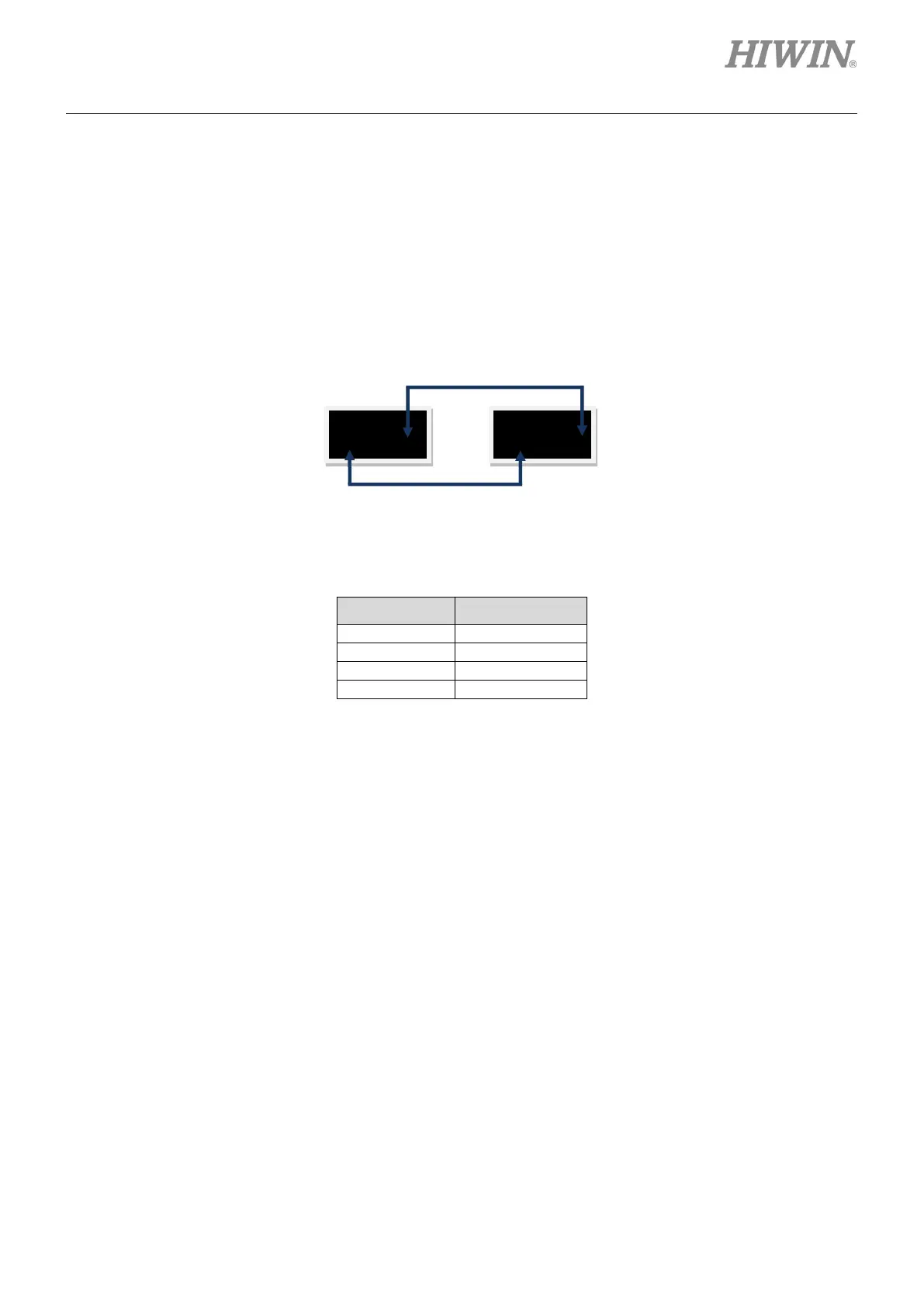
The status display for parameters O1 - O5 is shown in figure 7.4.2 and the symbol of status display is
described in table 7.4.2.
Figure7.4.2 Output status display
Table7.4.2 LCD displayed symbol for output status
LCD symbol Description
7.5 Change parameters page
The third page of LCD is the change parameters page, which is used to change the set parameter. The
operation can be divided into two zones: common parameter zone and advanced parameter zone. The
former is given in table 7.5.1 and the latter is given in table 7.5.3.1. In the change parameters page, press
the Up key or Down key to change the edited parameter. The operation flow chart is described in figure
7.5.1. The detailed operation procedure is described in the next subsection (take the LCD abbreviated
display symbol as an example).
 Loading...

