D2 Series Servo Drive User Manual Wiring
HIWIN MIKROSYSTEM CORP. 4-19
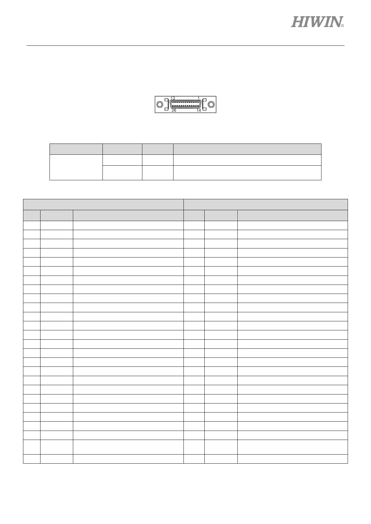
4.1.10 CN13/CN14 extension I/O signal
CN13 and CN14 are 26-pin SCSI connectors.
Figure4.1.10.1
Table4.1.10.1 Specification of extension I/O module
Connector Function Quantity Specification
CN13 and CN14
Digital input
24
Suitable for power system between 9 and 28 Vdc.
Digital output 12
Suitable for power system less than 24 Vdc.
Maximum allowable current: 100 mA.
Table4.1.10.2
CN13 CN14
Pin Signal Description Pin Signal Description
Positive terminal of digital output 1
Positive terminal of digital output 7
Negative terminal of digital output 1
Negative terminal of digital output 7
Positive terminal of digital output 2
Positive terminal of digital output 8
Negative terminal of digital output 2
Negative terminal of digital output 8
Positive terminal of digital output 3
Positive terminal of digital output 9
Negative terminal of digital output 3
Negative terminal of digital output 9
Positive terminal of digital output 4
Positive terminal of digital output 10
Negative terminal of digital output 4
Negative terminal of digital output 10
Positive terminal of digital output 5
Positive terminal of digital output 11
Negative terminal of digital output 5
Negative terminal of digital output 11
Positive terminal of digital output 6
Positive terminal of digital output 12
Negative terminal of digital output 6
Negative terminal of digital output 12
14 DI 1 Digital input 1 14 DI 13 Digital input 13
17 DI 4 Digital input 4 17 DI 16 Digital input 16
20 DI 7 Digital input 7 20 DI 19 Digital input 19
23 DI 10 Digital input 10 23 DI 22 Digital input 22
13 COM+/-
Input common point of (allowed for
positive or negative)
13 COM+/-
Input common point (allowed for
positive or negative)

 Loading...
