D2 Series Servo Drive User Manual Wiring
HIWIN MIKROSYSTEM CORP. 4-11
Do not insert more than two wires in the same socket.
Check that there is no short circuit between the wire and its adjacent wire after inserting the
wire.
Use the specific power voltage; otherwise it may cause fire or drive damage.
If the drive is used at the condition of poor or significantly fluctuating power, ensure that the
power is supplied within the specified range of voltage fluctuation; otherwise it may cause drive
damage.
Install
safety devices, such as breaker, to prevent the short circuit of external wiring from
damaging the drive.
The appropriate isolation and shielding measures must be adopted when the drive is used in
the following environments; otherwise it may cause the poor operation of drive.
Environment with the interference generated by the static electricity or the like.
Environment with a strong electric field or a strong magnetic field.
Environment with the emitted radiation.
Residual power still exists in capacitor even if main power is cut off. If you would like to stop the
motor right after the main power is cut off, refer to the instructions below.
Control power must be cut off at the same time.
Disable hardware enable by using relay.
Enable dynamic brake after main power is cut off.
4.1.3 CN2 brake/motor power
For frame A-C models, CN2 is the brake connector; while for the frame D model, CN2 is the motor power
connector. Check the pin assignment for each model before use. It is suggested that the brake power
should be independent power and does not use the same power source with other power.
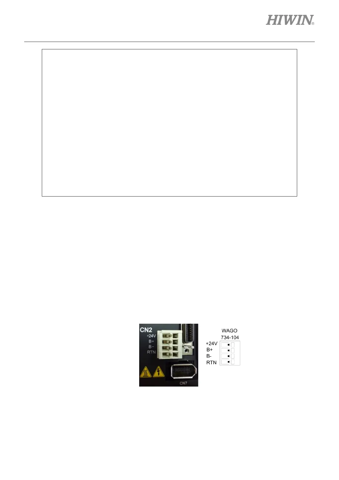
(1) Frame A-C
Use the brake wiring with a relay to connect the drive power of 24 Vdc to the brake.
Connector model: WAGO 734-104.
Figure4.1.3.1
 Loading...

