D2 Series Servo Drive User Manual Drive Configuration
HIWIN MIKROSYSTEM CORP. 5-51
5.5.4 Extension I/O
For D2 drive with the extension I/O module, parameters shown in table 5.5.4.1 can be used to set the
voltage level for each extension I/O pin.
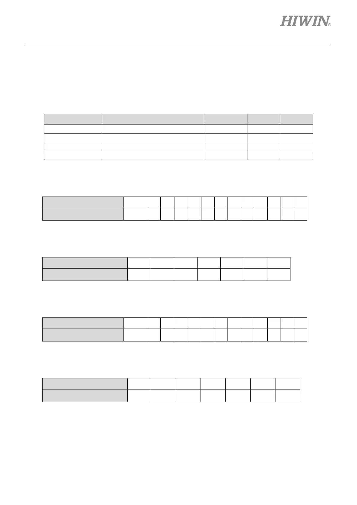
Table5.5.4.1 Extension I/O parameters
Parameter Definition Data Type Maximum Minimum
Inputs on the extension I/O CN13
Outputs on the extension I/O CN13
Inputs on the extension I/O CN14
Outputs on the extension I/O CN14
(1) Configured relationship between External_Input_1 and CN13
Table5.5.4.2
Bit No. of External_Input_1 15~12 11 10 9 8 7 6 5 4 3 2 1 0
Pin No. of CN13 - 25 24 23 22 21 20 19 18 17 16 15 14
(2) Configured relationship between External_Output_1 and CN13
Table5.5.4.3
Bit No. of External_output_1 15~6 5 4 3 2 1 0
Pin No. of CN13 - 12, 11 10, 9 8, 7 6, 5 4, 3 2, 1
(3) Configured relationship between External_Input_2 and CN14
Table5.5.4.4
Bit No. of External_output_2 15~12 11 10 9 8 7 6 5 4 3 2 1 0
Pin No. of CN14 - 25 24 23 22 21 20 19 18 17 16 15 14
(4) Configured relationship between External_Output_2 and CN14
Table5.5.4.5
Bit No. of External_output_2 15~6 5 4 3 2 1 0
Pin No. of CN14 - 12, 11 10, 9 8, 7 6, 5 4, 3 2, 1

 Loading...
