Drive Tuning D2 Series Servo Drive User Manual
6-22 HIWIN MIKROSYSTEM CORP.
6.6.1 Filter
The filter is located in the servo control loop on the inside of drive. Its main purposes are to eliminate the
control problem caused by the high-frequency vibration of system, and to deal with the resonant
frequency of overall mechanical system. The performance of system control can be enhanced via the
filter. D2 drive provides two filters that can be used simultaneously and set in the form of low pass filter or
notch filter. To design a filter, the frequency analyzer is usually used to analyze the system characteristic.
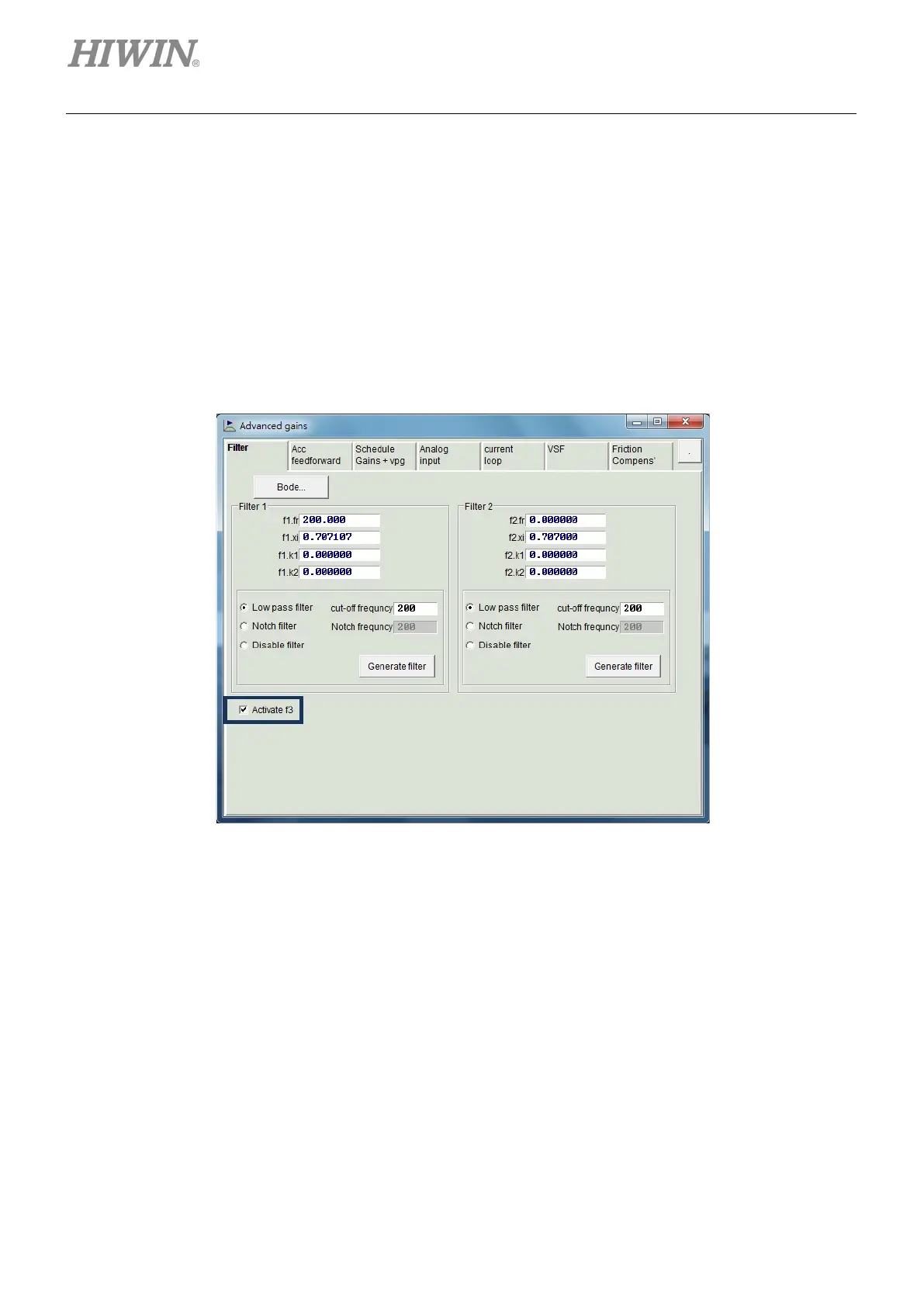
By clicking the “Bode…” button given in figure 6.6.1.1, the simulation interface of “Bode plot” is appeared
for the filter design. Settings of two common used filters are described in the following.
Figure6.6.1.1 Filter
Low pass filter
The setting of typical low pass filter is given as follows:
(1) fr: The cutoff frequency of filter. The unit is Hz. For general applications, a good effect can be
achieved at the setting of 500 Hz. Other cases can be considered to decrease this value.
However, the control performance will be reduced if the cutoff frequency is too small.
(2) xi: The damping ratio of filter. Its value ranges from 0 to 1.
(3) k1: 0.
(4) k2: 0.

 Loading...
