D2 Series Servo Drive User Manual Drive Tuning
HIWIN MIKROSYSTEM CORP. 6-23
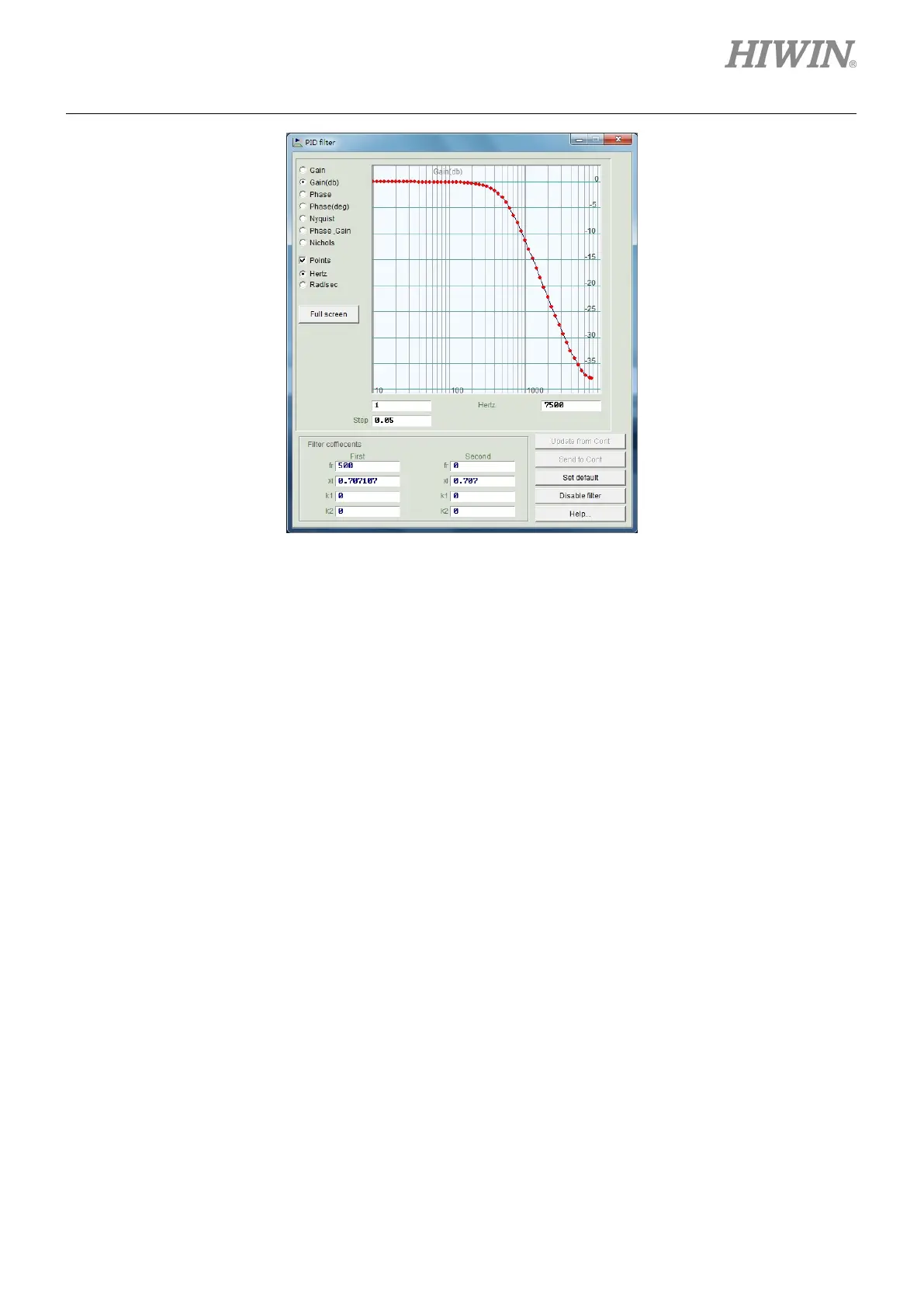
Figure6.6.1.2 Low pass filter
Notch Filter
When the system has an inappropriate resonance frequency (for example, between 10 and 250 Hz)
that cannot be eliminated by the mechanism correction or design enhancement, the notch filter can
be used to improve this problem. In general, the notch filter should be set according to the result of
frequency analysis. Refer to Section 6.6.3.
The setting of typical notch filter is given as follows:
(1) fr: The cutoff frequency of filter. The unit is Hz.
(2) xi: The damping ratio of filter. Its value ranges from 0 to 1. The closer to 0 this value is, the
narrower the filtering frequency band is; while the closer to 1 this value is, the wider the filtering
frequency band is.
(3) k1: 0.
(4) k2: 1.

 Loading...
