D2 Series Servo Drive User Manual Operation Principles
HIWIN MIKROSYSTEM CORP. 3-13
3.8 Error compensation
Normally, the positioning accuracy of drive is determined by the performance of encoder. But sometimes,
the encoder cannot completely meet the requirement of accuracy. In this case, instruments with the
higher level of accuracy (e.g. laser interferometer) should be applied to measure the system error. D2
drive has one high-performance control method. It saves the measured error data into the error map of
drive, as shown in figure 3.8.1, and uses this data during motion. By adopting the method of linear
interpolation between the fixed distance, it calculates the value of error compensation to enhance the
positioning accuracy.
Figure3.8.1
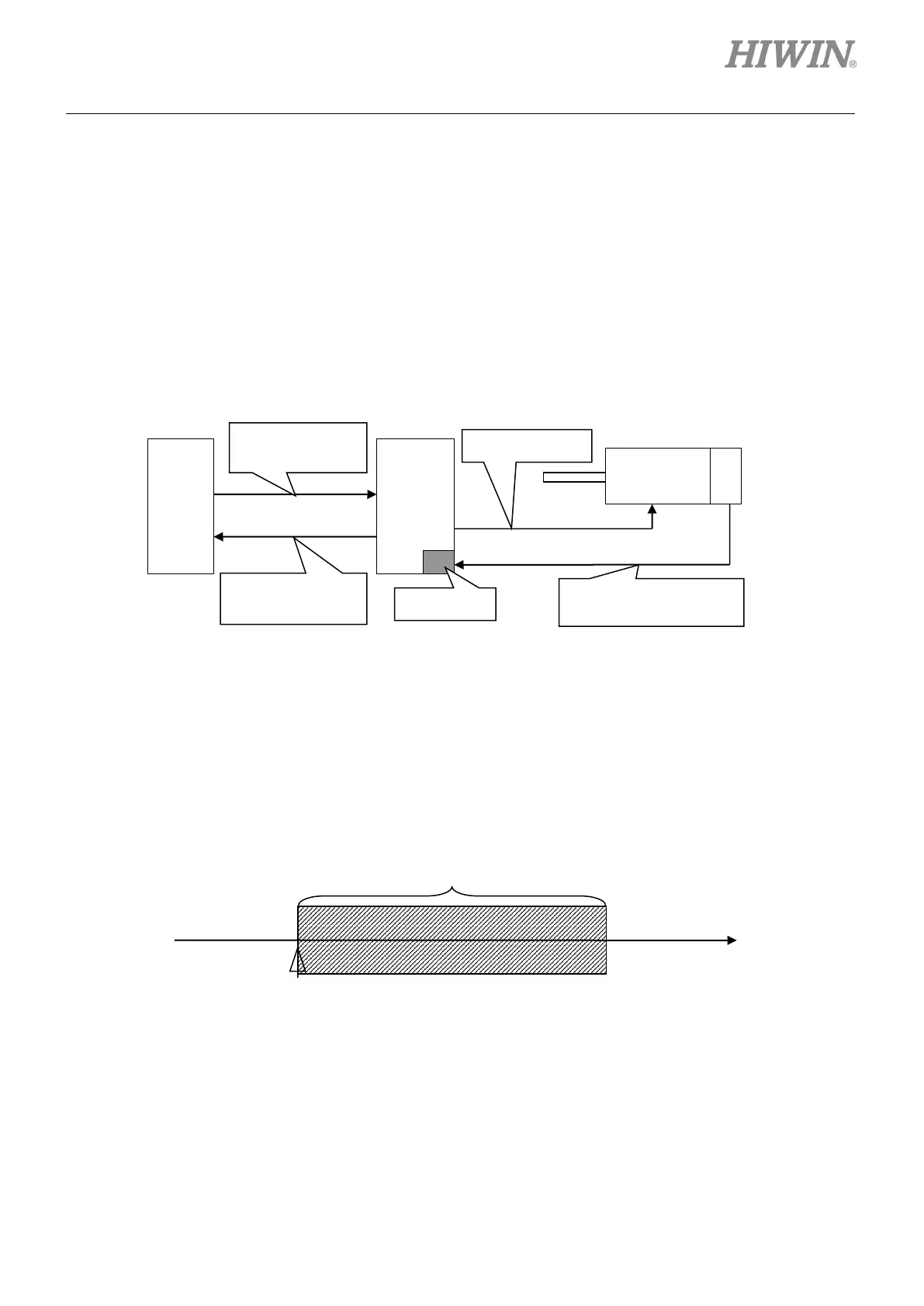
The mapping effective area is determined by the index signal. The area from the index towards positive
direction is the mapping effective area; while the area from the index towards negative direction is the
area without mapping. As shown in the following figure, the mapping effective area for non-zero home
offset is the same as that for zero home offset.
(1) Home offset = 0
Motor D2
drive
Feedback position
input from encoder
position output
index
Drive coordinate = 0
 Loading...

