Drive Configuration D2 Series Servo Drive User Manual
5-52 HIWIN MIKROSYSTEM CORP.
Example:
When DI 9 of CN13 (pin 22) is at the high level, DO 2 of CN13 (pin 3 and pin 4) outputs a high-level
signal.
#task/1;
_External_IOtest:
till(External_Input_1 & 0x0100 ); // Wait for DI 9 of CN13 to be high level.
External_Output_1 = 0x0002; // DO 2 of CN13 outputs a high-level signal.
ret;
5.6 In-position signal setting
In the servo system, the target position and the encoder feedback position have a certain following error.
When the motor moves to the target position, there will be a small period of settling, called the settling
time. Then, the motor enters the target radius. D2 drive provides the functional interface of in-position to
observe whether the motor has reached the target position by setting “Target radius” and “Debounce
time”. This function is supported only when the drive is operated in the position mode or stand-alone
mode. The “In-Position” status can be sent to the host controller via the digital output signal.
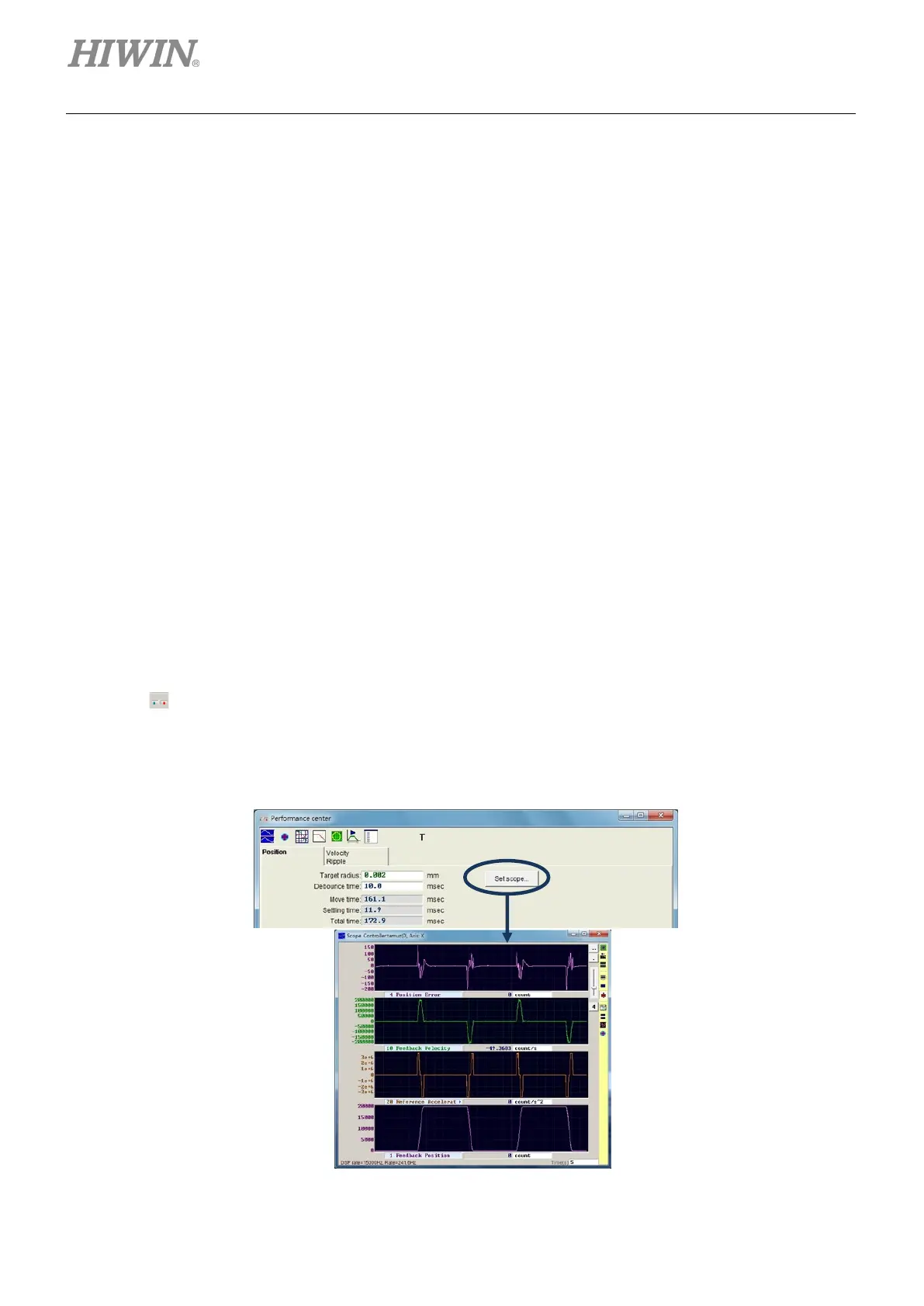
Function setting
Click
to appear the window of performance center. The “In-Position” configuration page is
displayed in the “Position” tab. Click the “Set scope…” button to open the “Scope” window if
capturing the waveform is needed. The default of “In-Position” signal is O2. Refer to Section 5.5.2 for
setting digital output.
Figure5.6.1

 Loading...
