D2 Series Servo Drive User Manual Operation Principles
HIWIN MIKROSYSTEM CORP. 3-11
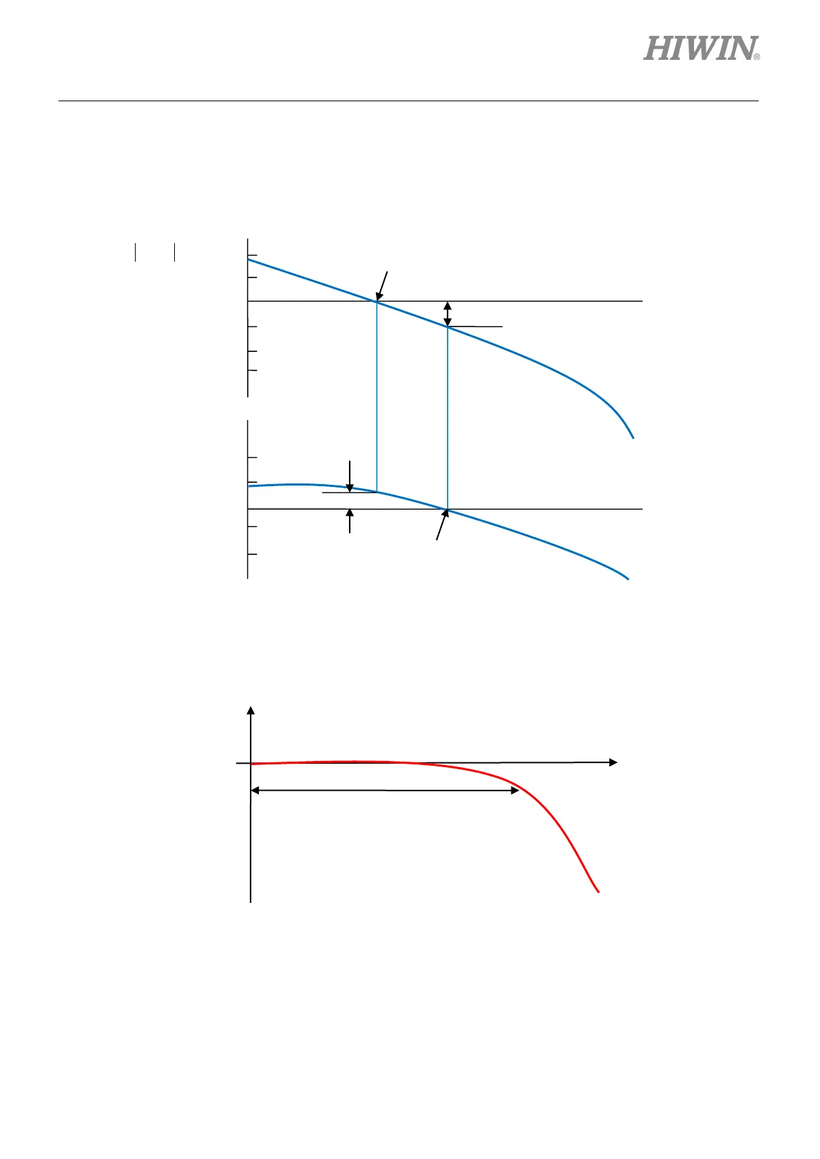
3.6.2 Bode diagram
The gain margin and phase margin of Bode diagram are given in figure 3.6.2.1.
Figure3.6.2.1 Gain margin and phase margin of Bode diagram
The bandwidth of Bode diagram is defined as the frequency at -3 dB, as shown in figure 3.6.2.2.
Figure3.6.2.2 Bandwidth of Bode diagram
p
margin

 Loading...
