D2 Series Servo Drive User Manual Drive Tuning
HIWIN MIKROSYSTEM CORP. 6-41
6.7.2.3 Bode
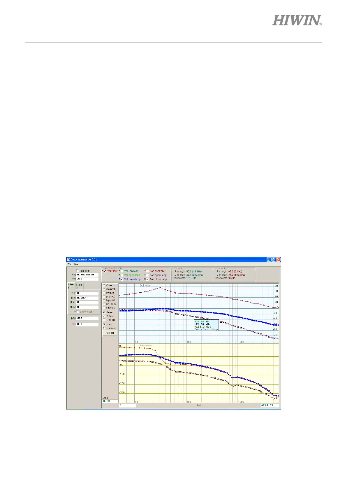
The “ph + gain” option of “Loop constructor” can analyze and simulate frequency responses of “Vel
controller”, “Vel open loop”, “Vel close loop”, “Pos controller”, “Pos open loop”, and “Pos close loop” of
control system. Using the check method can select to analyze and simulate the Bode diagram of velocity
loop or position loop. It can also select six loops to analyze and simulate at the same time. Bode plots of
“Vel close loop” and “Pos close loop” are shown in figure 6.7.2.3.1. Clicking the curve on the Bode plot
displays the value of frequency response for the analysis of control system.
(1) Vel controller (Velocity controller): The frequency response of velocity controller.
(2) Vel open loop (Velocity open loop): The frequency response of the velocity open loop of control
system.
(3) Vel close loop (Velocity close loop): The frequency response of the velocity close loop of control
system.
(4) Pos controller (Position controller): The frequency response of position controller.
(5) Pos open loop (Position open loop): The frequency response of the position open loop of control
system.
(6) Pos close loop (Position close loop): The frequency response of the position close loop of control
system.
Figure6.7.2.3.1 Bode plots of velocity close loop and position close loop
 Loading...

