D2 Series Servo Drive User Manual Wiring
HIWIN MIKROSYSTEM CORP. 4-17
Pin Signal Function
45 CWH-
Channel 1: Pulse, CW, A-phase
Maximum voltage: 12 V
High-speed (4 Mpps) pulse command
47 CCWH-
Channel 2: DIR, CCW, B-phase
Maximum voltage: 12 V
Common point for general-purpose input signal (Sink or Source)
General-purpose input signal (programmable function)
D2 model: N/A; D2T model: I10.
General-purpose output signal (programmable function)
40 N/A or O5+
D2 model: N/A; D2T model with the frame A, B, or C: O5+;
D2T model with the frame D: brake output/O5+.
12 N/A or O5-
D2 model: N/A; D2T model with the frame A, B, or C: O5-;
D2T model with the frame D: brake output/O5-.
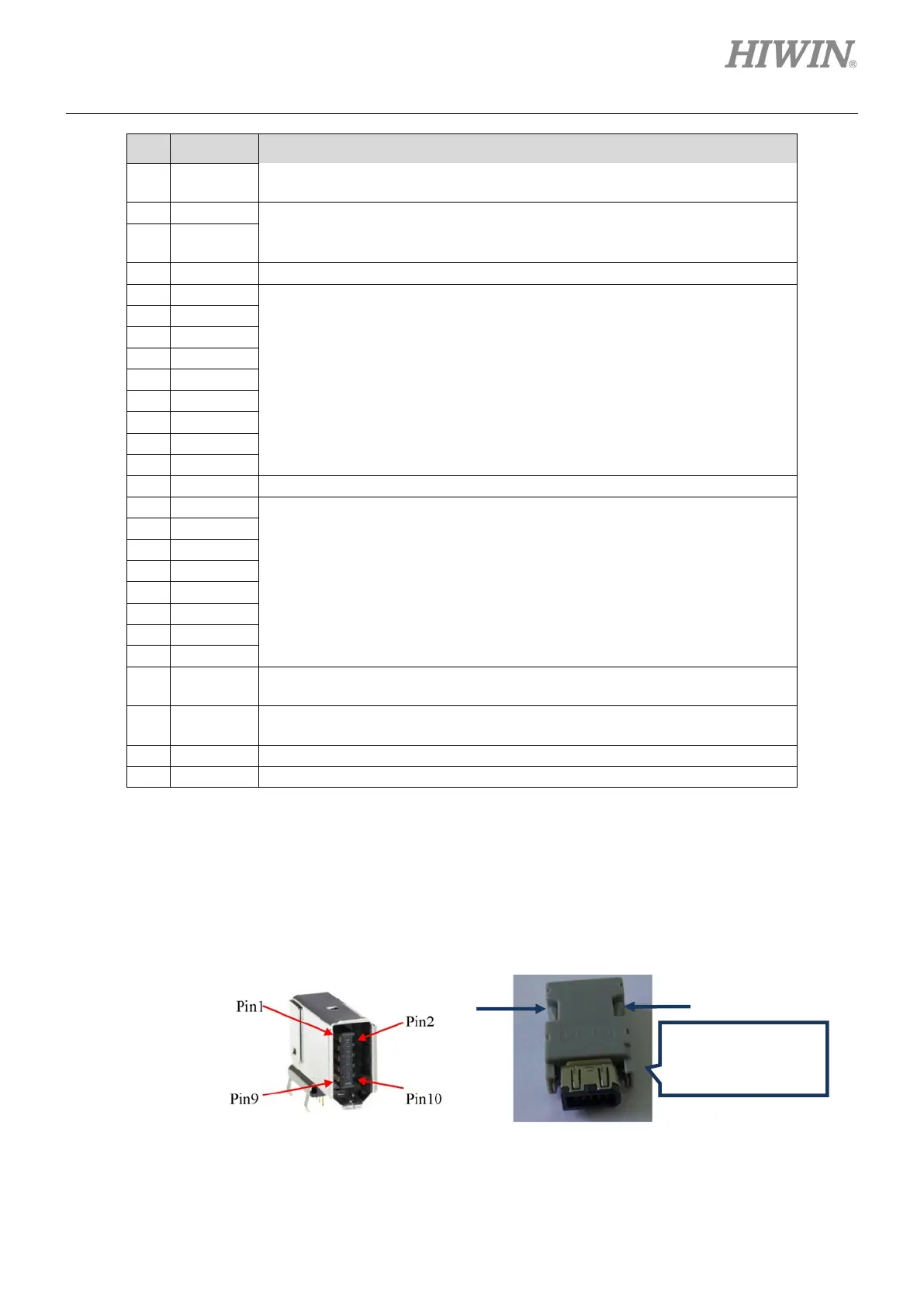
4.1.8 CN7 encoder
Press and pull clamps on both sides to remove CN7 connector.
Figure4.1.8.1
clamps to remove
CN7 connector
(a) SCR connector 10 pin (male)
(b) SCR connector 10PIN (female)
 Loading...

