Specifications D2 Series Servo Drive User Manual
2-4 HIWIN MIKROSYSTEM CORP.
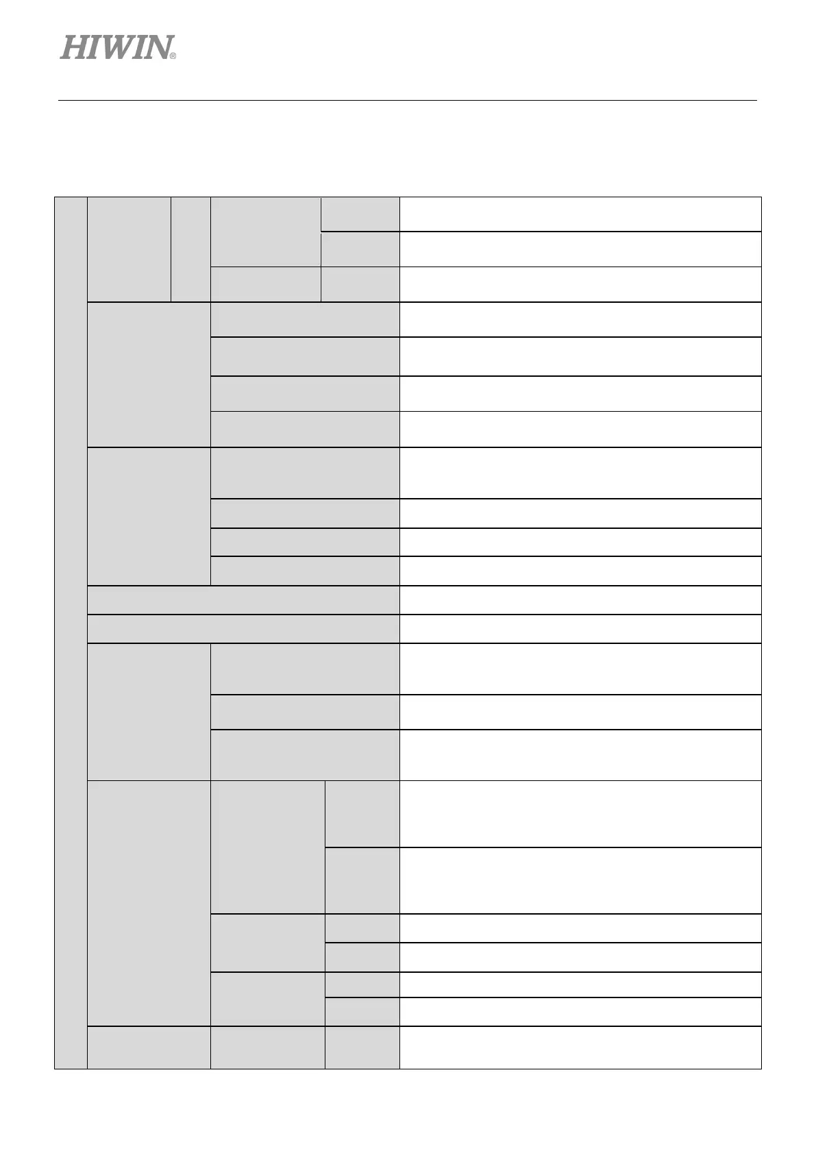
2.2 Drive specifications
Table2.2.1 Drive specification
Basic specifications
Input power
220V
Main power
Single/three-phase, 200 - 240 Vac 50/60Hz
Three-phase, 200 - 240 Vac 50/60Hz
Control power
Single-phase, 200 - 240 Vac 50/60Hz
Output power
Power
Frame A: 100 W; frame B: 400 W; frame C: 1.0 KW;
frame D: 2.0 KW.
Continuous current
Frame A: 0.9 A
rms
; frame B: 2.5 A
rms
;
rms
rms
Peak current
rms
rms
;
frame C: 15.3 A
rms
; frame D: 33 A
rms
.
Sustainable duration of peak
current
1 second maximum.
Environment
Temperature
Operation temperature: 0°C to 45°C
(if over 55°C, the forced ventilation is needed)
Storage temperature: -20°C to 65°C
Humidity 0 to 90% RH (non-condensing)
Altitude Below 1,000 meters
Vibration 1G (10 to 500Hz)
Installation pollution level II
Control method IGBT PWM space vector control
Encoder input
Resolution/Feedback
resolution
13-bit (10,000 count/rev) less-wire incremental encoder;
17-bit (131,072 count/rev) serial incremental encoder (5
Frequency
5M pulse/sec (Before Quadrature);
20M count/sec (After Quadrature).
Other
For the dual-loop model, the rotary encoder should be the
17-bit serial absolute encoder and the linear encoder
should be the digital AqB encoder.
Parallel I/O
connector
Control signal
Input
9 (general purpose) for D2 model
10 (general purpose) for D2T model
Optical coupler component, general-purpose input
5 V/1 mA, 24 V/5 mA (Each input pin)
Output
4 (general purpose) for D2 model
5 (general purpose) for D2T model
Optical coupler component, general-purpose output
24 V/0.1 A (Each output pin)
Analog signal
Input 1 (12-bit A/D)
Output 2 (analog monitor: 2 outputs)
Pulse signal
Input 2 (low-speed channel, high-speed channel)
Output 4 (line driver: 3 outputs; open collector: 1 output)
Brake connector Control signal Output
Used to connect with brake (1 Adc max). Also, it is
programmable for general-purpose output.

 Loading...
