Wiring D2 Series Servo Drive User Manual
4-18 HIWIN MIKROSYSTEM CORP.
Table4.1.8.1
Description
Encoder power output of +5 Vdc
Digital ground and ground for +5 Vdc
17-bit incremental: timing output for
serial communication (MA+, MA-)
17-bit absolute and dual-loop
architecture: data transmission for
serial communication (PS+, PS-)
4 N/A MA- PS- PS-
13-bit incremental: digital signal
transmission (A, /A, B, /B, Z, /Z)
17-bit incremental: data transmission
for serial communication (SL+, SL-)
Dual-loop architecture: digital signal
transmission (Connecting to linear
encoder)
Shield FG FG FG FG Frame ground reference
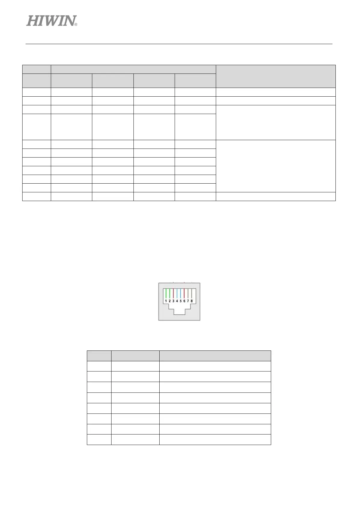
4.1.9 CN8 EtherCAT communication
To connect with the EtherCAT module, the connector of network cable should have the shielding
protection.
Figure4.1.9.1 CN8 connector
Table4.1.9.1 CN8 pin assignment
Pin Signal Function
1 TX+ Positive terminal of data transmit
2 TX- Negative terminal of data transmit
3 RX+ Positive terminal of data receive
4 EtherCAT Gnd EtherCAT signal ground
5 EtherCAT Gnd EtherCAT signal ground
6 RX- Negative terminal of data receive
7 EtherCAT Gnd EtherCAT signal ground
8 EtherCAT Gnd EtherCAT signal ground
 Loading...

