Operation Principles D2 Series Servo Drive User Manual
3-14 HIWIN MIKROSYSTEM CORP.
(2) Home offset = 100
Figure3.8.2
3.9 Velocity ripple
Generally in the motion control, it is always desirable that the motion in the constant-speed phase is as
smooth as possible. The motion stability can be estimated by the index of velocity ripple. Main factors
causing the variation in the constant-speed phase are the motor cogging force, cable chain, air pipeline,
and guideway friction, and so on. This velocity ripple is usually used for scanning or detecting machines
required high stability in the constant-speed phase. The equation of velocity ripple is:
%,
RippleVelocity 100
2
1
×
−
±=
V
VV
target
minmax
where V
target
is the target velocity, V
max
is the maximum velocity in the constant-speed phase, and V
min
is
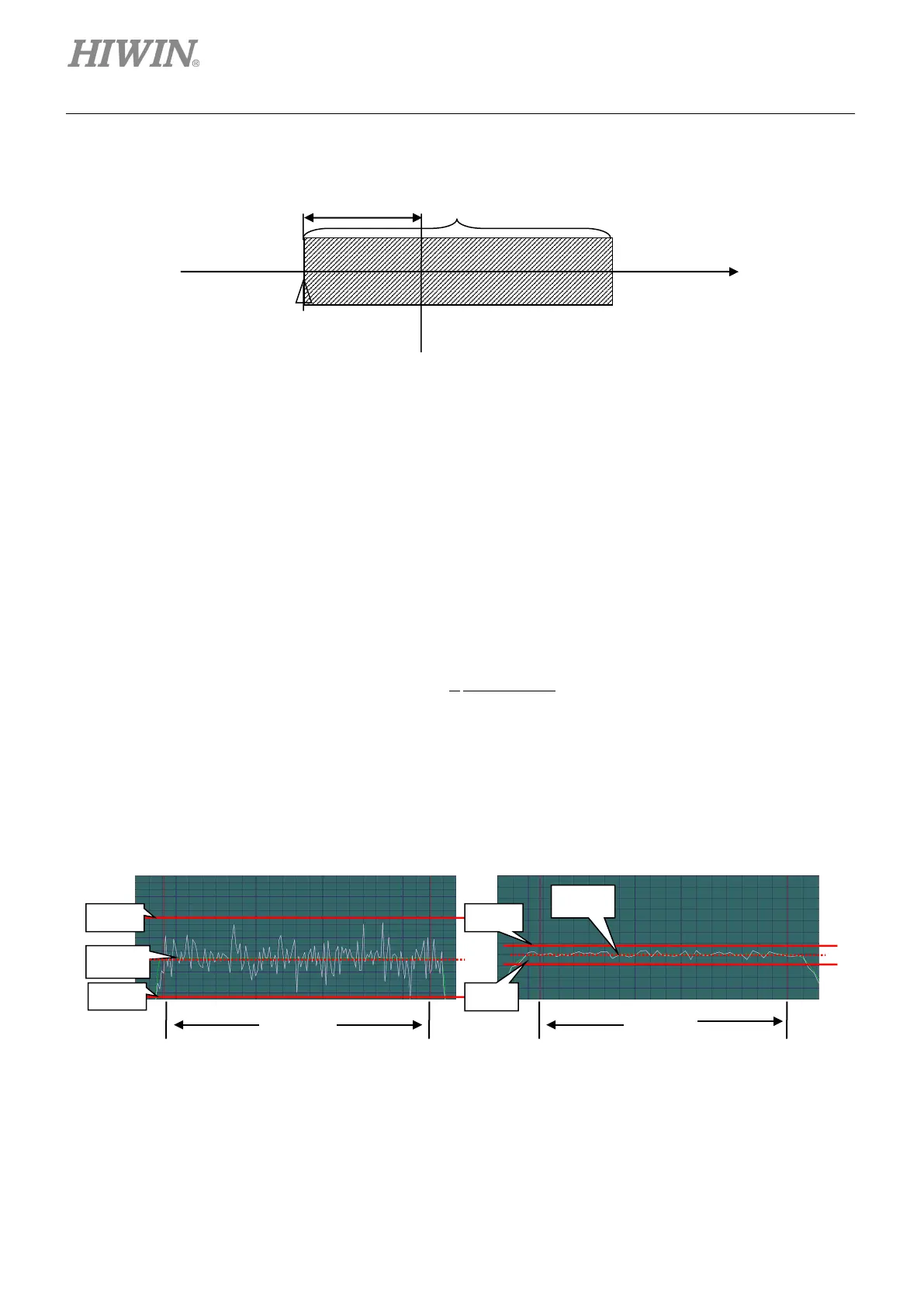
the minimum velocity in the constant-speed phase. As shown in figure 3.9.1, the velocity ripple of (a) is
larger indicated less steadiness; while (b) is smaller indicated better steadiness.
Figure3.9.1
= 100
Velocity
target
target
 Loading...

