D2 Series Servo Drive User Manual Drive Configuration
HIWIN MIKROSYSTEM CORP. 5-45
(4) Invert state
If required, this option can be checked to reverse the polarity of output state to match the host
controller.
Note:
The internal logic of drive is not affected by this “Invert State” setting at all.
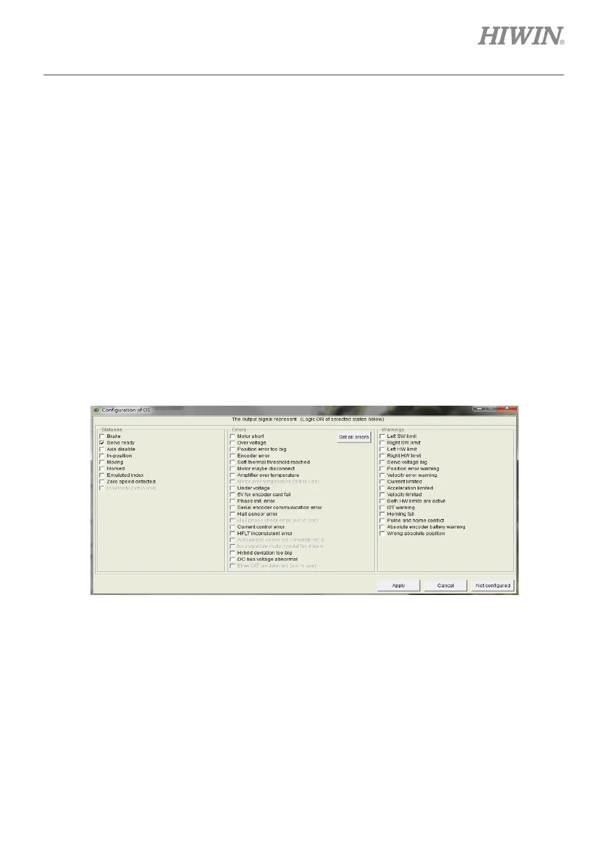
(5) Output function setting
Each output pin has one corresponding “Configure” setting button. Taking O1 as an example, click
the “Configure O1” button to open the “Configuration” window. This menu can be divided into three
categories: “Statuses”, “Errors”, and “Warnings”, as shown in figure 5.5.2.2 two or more items are
selected in the same configuration category, the output function works when one of these items is
triggered. If all checked options need to be cancelled, click the “Not Configured” button. After
selecting the desired function, click the “Apply” button to complete the setting. On the other hand,
click the “Cancel” button to discard the setting. In the “Errors” category, there is one “Set all errors”
button. It is recommended to use this button at selecting all errors in the “Errors” category. This is
helpful to quickly complete the setting.
Figure5.5.2.2 Output function setting
 Loading...

