4. Connect each power supply to the power sources. Insert the coupler end of the power cord into the
AC power cord inlet on the AC power supply faceplate.
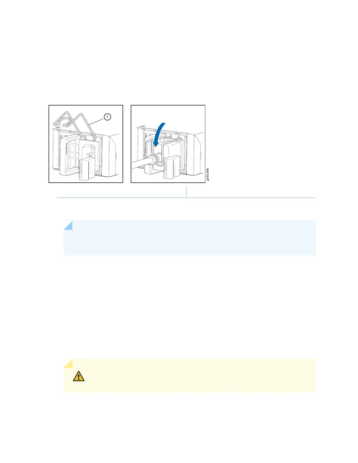
5. Push the power cord retainer onto the power cord (see Figure 63 on page 270).
Figure 63: Connecting an AC Power Cord to an AC Power Supply in a QFX5110
1—Power cord retainer
6. If the AC power source outlet has a power switch, set it to the off (O) position.
NOTE: The switch powers on as soon as power is provided to the power supply. There is no
power switch on the device.
7. Insert the power cord plug into an AC power source outlet.
8. If the AC power source outlet has a power switch, set it to the on (|) position.
9. Verify that the AC and DC LEDs on each power supply are lit green.
If the amber fault LED is lit, remove power from the power supply, and replace the power supply (see
Removing a Fan Module from a QFX5110). Do not remove the power supply until you have a replacement
power supply ready: the power supplies or a blank cover panel must be installed in the switch to ensure
proper airflow.
CAUTION: Replace a failed power supply with a blank panel or new power supply
within one minute of removal to prevent chassis overheating.
270

 Loading...


