NOTE: Each power supply must be connected to a dedicated power source outlet.
The power supply slots are at the right end of the rear panel on 24-port and 48-port switches,
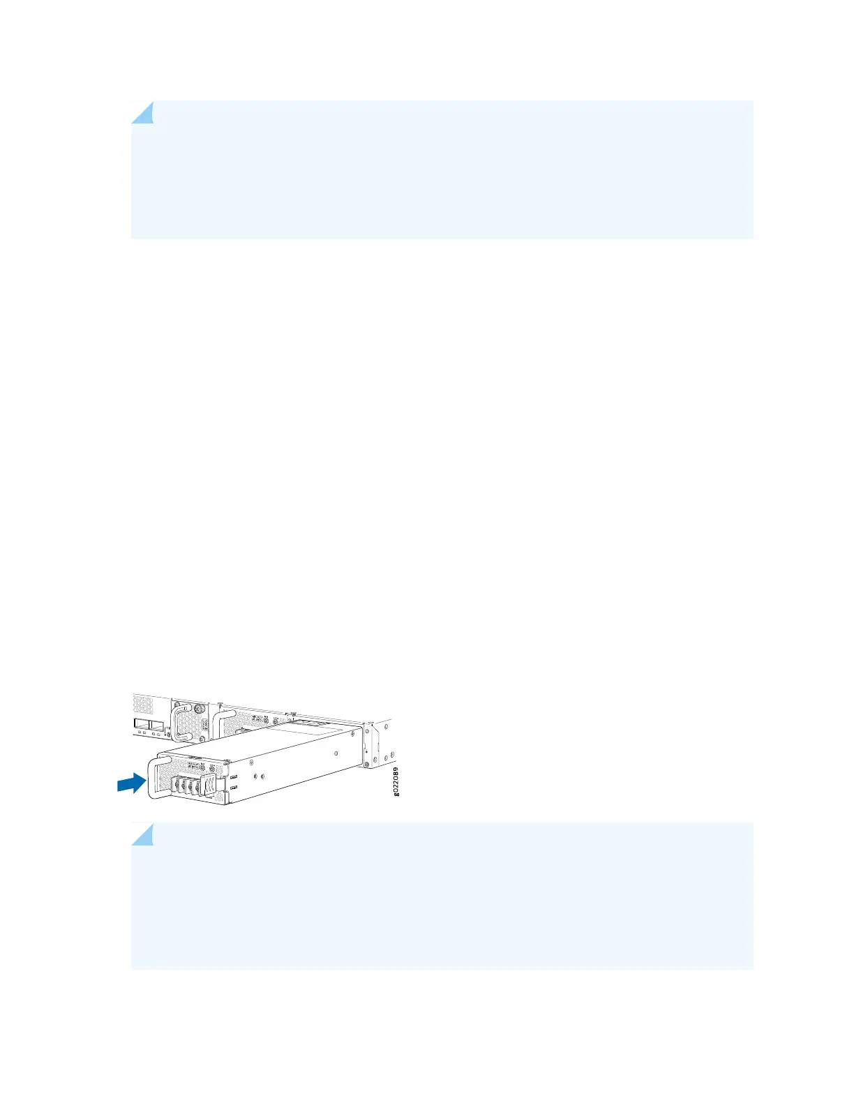
and at the left end on 32-port switches. Figure 167 on page 468 shows how to install a DC power
supply in 24-port or 48-port switches. The procedure is the same for 32-port switches.
To install a DC power supply in the switch:
1. Ensure that you have the correct power supply. The label AIR IN (AFI) or AIR OUT (AFO) on the power
supply must match the label AIR IN (AFI) or AIR OUT (AFO) on the installed fan module.
2. Attach the ESD grounding strap to your bare wrist, and connect the strap to the ESD point on the
chassis.
3. If the power supply slot has a cover panel on it, loosen the captive screws on the cover panel by using
your fingers or the screwdriver. Hold the captive screw and gently pull it outward to remove the cover
panel. Save the cover panel for later use.
4. Taking care not to touch power supply pins, leads, or solder connections, remove the power supply
from the bag.
5. Using both hands, place the power supply in the power supply slot on the rear panel of the switch and
slide it in until it is fully seated and the ejector lever fits into place.
Figure 167: Installing a DC Power Supply in an EX4300 Switch
NOTE: If you have a Juniper J-Care service contract, register any addition, change, or upgrade
of hardware components at
https://www.juniper.net/customers/support/tools/updateinstallbase/ . Failure to do so can
result in significant delays if you need replacement parts. This note does not apply if you replace
existing components with the same type of component.
468

 Loading...


