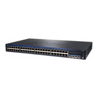
Table 114: Chassis Viewer for EX4600 Switches (continued)
DescriptionField
You can install an expansion module in the PIC 1 and PIC 2 slots. If you have
installed an expansion module, mouse over the ports in the module to view the
details of the ports in module.
When you install a transceiver in the port, the following colors denote the interface
status:
•
Green—Interface is up and operational.
•
Yellow—Interface is up but is not operational.
•
Gray—Interface is down and not operational.
PIC 1 and PIC 2 slots
NOTE:
•
In EX4600 switches the LEDs are seen in the front panel; these are not active.
•
In EX4600 switches there is no LCD panel.
Rear View of the EX4600 Switch
The management ports (RJ-45 and SFP) is used to connect the switch to a
management device for out-of-band management.
Management port
The Console port (RJ-45) is used to connect the switch to a management console
or to a console server.
Console port
Indicates the USB port for the switch.
NOTE: We recommend that you use USB flash drives purchased from Juniper
Networks for your EX Series switch.
USB port
Mouse over the fan tray icons to display name, status, and description information.Fan tray
Mouse over the power supply icons to display name, status, and description
information.
Power supplies
Table 115: Chassis Viewer for EX4650 Switches
DescriptionField
Front View
Displays 48 small form-factor pluggable (SFP28) ports and eight 100-Gbps quad
small form-factor pluggable (QSFP28) ports.
Mouse over the interface (port) to view more information.
SFP28 and QSFP28 Ports
557

 Loading...


