provides a frame-oriented interface to the ATM layer. The integrated local
management interface (ILMI) provides local management across the UNI.
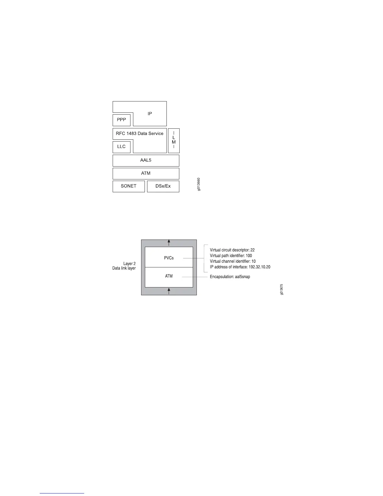
Figure 14: Structure of ATM Protocol
Figure 15 on page 20 shows sample configuration parameters for a typical ATM
interface configuration.
Figure 15: ATM Interface Configuration Parameters
The following sample command sequence configures an ATM interface on port 0 of
the line module in slot 1. See JUNOSe Link Layer Configuration Guide, for information
about how to configure an ATM interface.
host1(config)#interface atm 0/1
host1(config-if)#interface atm 0/1.22
host1(config-if)#atm pvc 22 100 10 aal5snap
host1(config-subif)#ip address 192.32.10.20 255.255.255.0
Configuring IP/PPP
The router supports IP/PPP on the channelized T3, E1, and T3/E3 interfaces and
IP/PPP/SONET on the OC3/STM1 and OC12/STM4 interfaces. This support allows
service providers to accept traffic from subscribers who have CPE equipment, such
as routers with PPP interfaces, and to transmit traffic in PPP format to other network
devices.
Figure 16 on page 21 shows that the router supports the incoming IP/PPP traffic
from the CPE. This traffic can then be routed to the uplink(s) attached to the router
or to other CPEs that are attached to the router.
20 ■ Configuring Data Link-Layer Interfaces
JUNOSe 11.1.x System Basics Configuration Guide