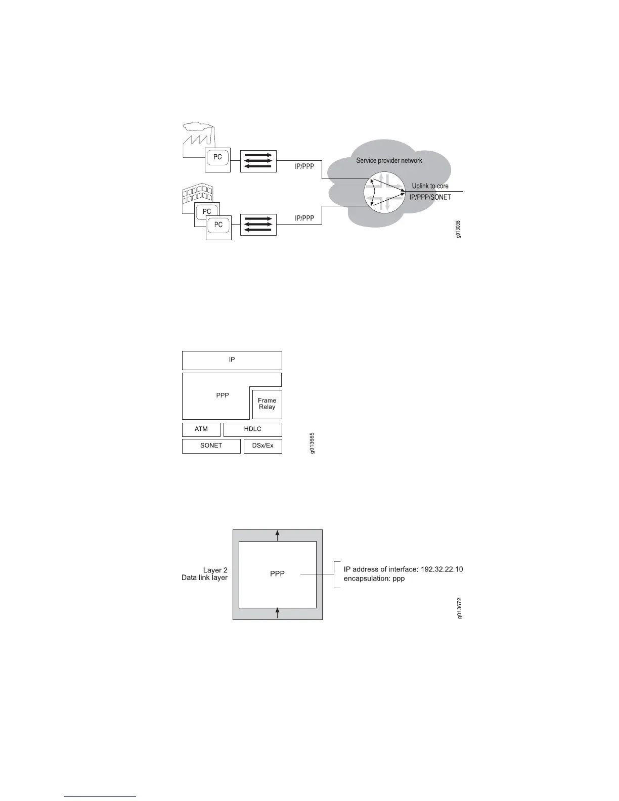
Figure 16: IP/PPP Connections from the CPE on an E Series Router
As shown in Figure 17 on page 21, the PPP protocol can exist directly on top of the
HDLC layer or on top of a layer 2 Frame Relay or ATM interface. In either case, IP
rides on top of PPP, providing support for IP/PPP/ATM, IP/PPP/HDLC, and
IP/PPP/Frame Relay. Both SONET and DSx/Ex interfaces are supported at the physical
layer.
Figure 17: Structure of PPP
Figure 18 on page 21 shows sample configuration parameters for PPP on a serial
interface.
Figure 18: PPP Interface Configuration Parameters
The following sample command sequence configures PPP on a serial interface. See
JUNOSe Link Layer Configuration Guide, for details.
host1(config)#interface serial 3/0:2/5
host1(config-if)#encapsulation ppp
host1(config-if)#ip address 192.32.22.10 255.255.255.0
Configuring Data Link-Layer Interfaces ■ 21
Chapter 1: Planning Your Network