TOS93 Series User’s Manual 287
Specifications | Withstanding voltage test section
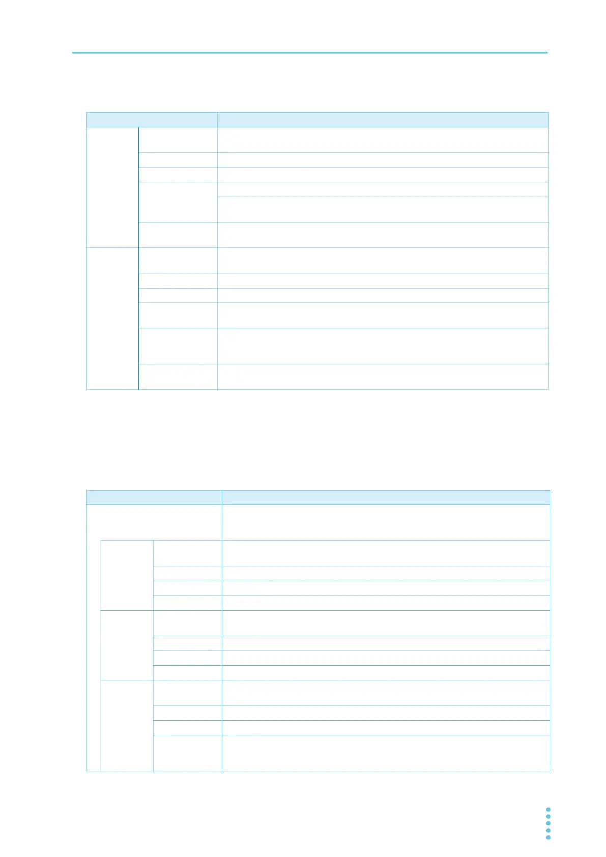
Measurement function
Judgment function
Item Specifications
Voltmeter Measurement
range
0.00 kV to 7.50 kV AC/DC
Resolution 0.1 V
Accuracy ±(1.2 % of reading + 5 V)
Response Can be switched between true rms and mean-value response rms conversion.
Peak-value response in a separate system (the peak-value response is for
measuring the dielectric breakdown voltage while rising)
Hold function The voltage measurement after a test is finished is held while the pass/fail judgment
is displayed.
Ammeter
1
2
Measurement
range
AC: 0.00 mA to 110 mA, DC: 0.00 mA to 22 mA
(Current including the active component and reactive component)
Accuracy ±(1 % of reading + 2 μA) (active component)
Response Can be switched between true rms and mean-value response rms conversion.
Hold function The current measurement after a test is finished is held while the pass judgment is
displayed.
Offset cancel
function
Cancels up to 10 mA of the current flowing through the insulation resistance and stray
capacitance components across output cables and the like (resistance component
only for DC tests). OFF function available.
Calibration Active component: Calibrated with the rms of a sine wave using a pure resistive load.
Reactive component: Not calibrated.
1 During AC voltage tests, current also flows in the stray capacitance of items such as the test leads and tools. For details
on stray capacitance, see “Stray Capacitance of AC Withstanding Voltage Tests” (p.321).
2 When the temperature and humidity are high, erroneous current from the product’s internal and external high-voltage
wir
ing sections to ground increases. When the humidity exceeds 70 %, an erroneous current of about 50 µA may be
generated.
Item Specifications
Current judgment operation The output is shut off when a judgment is made. Buzzer volume level can be set in
the range of 0 (OFF) to 10 for pass and fail separately. In an auto test, the buzzer is
valid only for the judgment that takes place at the end of the program.
UPPER
FAIL
Judgment
method
UPPER FAIL results when a current greater than or equal to the Upper limit is
detected. For DCW, judgment is not made during the judgment delay (Judge Delay).
Display “Upper-FAIL” is displayed.
Buzzer On
SIGNAL I/O The Upper-FAIL signal is generated continuously until a STOP signal is received.
LOWER
FAIL
Judgment
method
LOWER FAIL results when a current less than or equal to the Lower limit is detected.
Judgment is not made during Voltage rise time or Voltage fall time of an ACW test.
Display “Lower-FAIL” is displayed.
Buzzer On
SIGNAL I/O The Lower-FAIL signal is generated continuously until a STOP signal is received.
PASS Judgment
method
PASS judgment is made if Upper-FAIL or Lower-FAIL has not occurred when the test
time elapses.
Display “PASS” is displayed.
Buzzer On (fixed to 50 ms)
SIGNAL I/O The PASS signal is generated for the length of time specified by the Pass Hold
setting. If Pass Hold is set to Infinity, the PASS signal is generated continuously until
a STOP signal is received.