288 User’s Manual TOS93 Series
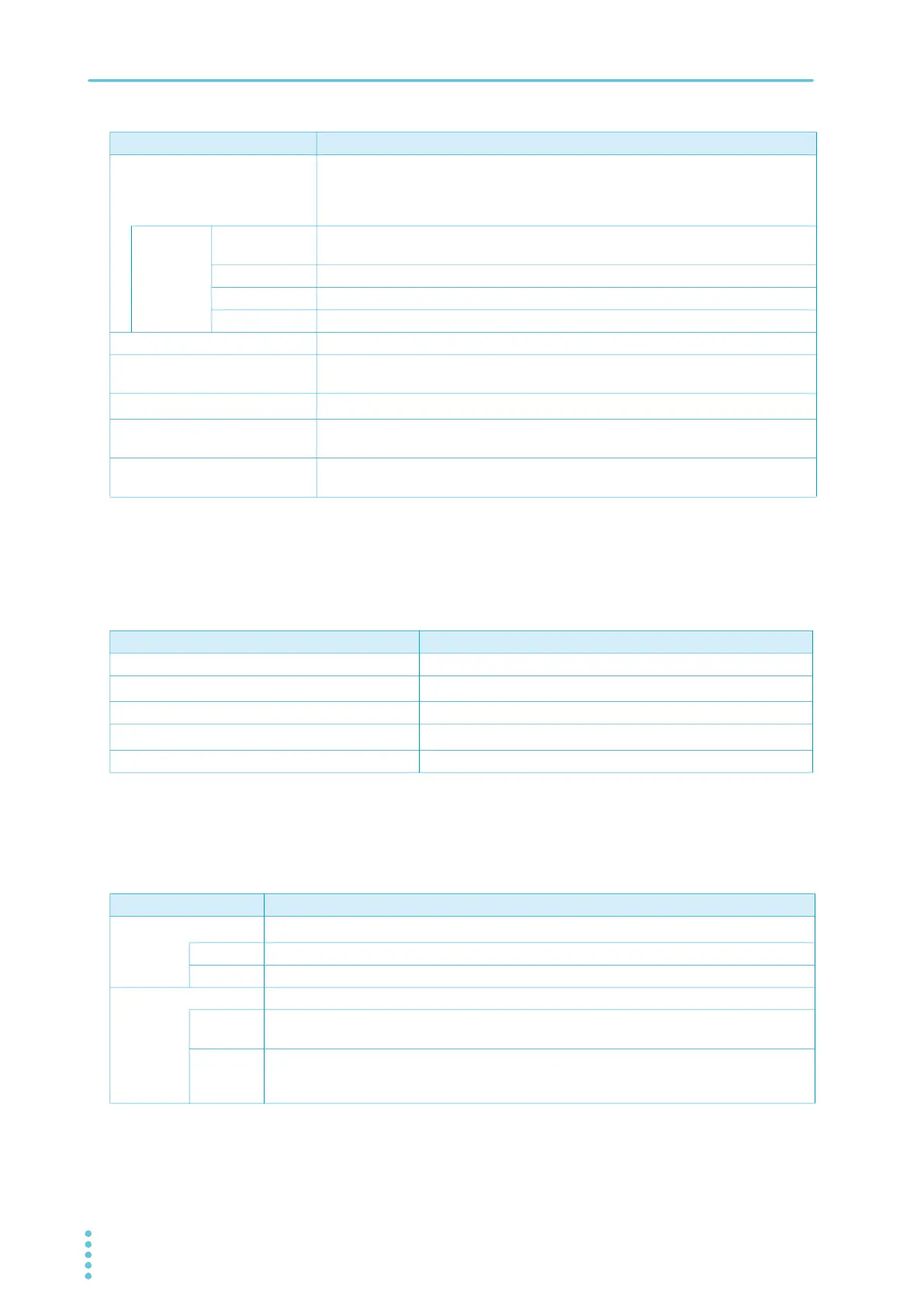
Specifications | Withstanding voltage test section
Timer function
Other specifications
Voltage rise rate
judgment operation
Monitors the voltage rise rate during Voltage rise time. This is valid when Auto
setting of the judgment delay (Delay Auto) is set to on and the output voltage is
200 V or more. The output is shut off when a judgment is made. Buzzer volume level
can be set in the range of 0 (OFF) to 10 for pass and fail separately.
dV/dt FAIL Judgment
method
When the voltage rise rate (dV/dt) is less than approx. 1 V/s.
Display “Upper-FAIL (dV/dt)” is displayed.
Buzzer ON
SIGNAL I/O The U FAIL signal is generated continuously until a STOP signal is received.
Upper limit setting range AC: 0.01 mA to 110.00 mA, DC: 0.01 mA to 21.00 mA
Lower limit setting range AC: 0.00 mA to 109.99 mA, DC: 0.00 mA to 20.99 mA, OFF. Setting 0.00 is
equivalent to OFF.
Judgment accuracy
1
2
±(1 % of setting + 5 μA)
Current detection method Compares to the reference value using the following method.
Calculate true rms values, convert mean-value responses to rms values
Response speed (filter) switching Switches the current detection response speed (sensitivity) used in UPPER FAIL
judgment between five levels in ACW and DCW tests.
1 During AC voltage tests, current also flows in the stray capacitance of items such as the test leads and tools. For details
on stray capacitance, see “Stray Capacitance of AC Withstanding Voltage Tests” (p.321).
2 When the temperature and humidity are high, erroneous current from the product’s internal and external high-voltage
wir
ing sections to ground increases. When the humidity exceeds 70 %, an erroneous current of about 50 µA may be
generated.
Item Specifications
Item Specifications
Voltage rise time settings range 0.1 s to 200.0 s
Voltage fall time setting time
1
0.1 s to 200.0 s, OFF
Test time setting range 0.1 s to 1 000.0 s, OFF
Judgment delay (Judge Delay) setting range
2
0.1 s to 100.0 s, AUTO
3
(DCW only)
Accuracy ±(100 ppm of setting + 20 ms) (excluding the fall time)
1 This setting is used only when a PASS judgment occurs in ACW and DCW tests. During a DCW test, the voltage may
not drop all the way within the set time because of the electrostatic capacity inside the product and the EUT.
2 Less than the sum of the rise time and fall time.
3 If Delay Auto is set to on, LOWER judgment is not made until the charge time ends.
Item Specifications
Analog monitor
1
Outputs a voltage signal according to the current waveform or voltage waveform
I Current waveform: Scale 50 mA/1 V
V Voltage waveform: Scale 1 kV/1 V
Grounding mode (GND) Can be switched between Low and Guard.
Low GND is connected to the low terminal. Measures the current flowing across the low terminal
and chassis (normal applications).
Guard
2
GND is connected to Guard. Measures only the current flowing through the low terminal
(current flowing through the chassis is not measured) (high sensitivity, high accuracy
measurement applications).
1 Monitor signal output is isolated from the chassis (earth). If you connect an oscilloscope or an external device whose
BNC shield is grounded, be sure to set the grounding mode (GND) to Guard. The value is not calibrated.
2 If there is a possibility that the EUT or tools and the like will be grounded or if you are uncertain, do not set GND to
Guard. Doing so is extremely dangerous because the ammeter will be shorted and will not be able to measure current.
For normal applications, set GND to Low.