TOS93 Series User’s Manual 291
Specifications | Insulation resistance test section
Judgment function
2 If the grounding mode (GND) is set to low in a highly humid environment, leakage current to ground will be generated
from the high-voltage wiring sections inside the product and the high-voltage wiring sections between the product and
the EUT. This leakage current ranges from several nA to several tens of nA depending on the usage and wiring
conditions of the optional TOS9320 high voltage scanner and greatly affects measurement accuracy. The effects of
leakage current can be reduced by making measurements with the offset enabled.
3 Add 10 % to the accuracy when measuring 100 V or less.
4 Add 5 % to the accuracy when measuring 100 V or less.
5 When the measured current is limited to 100 nA or more (no condensation) when the humidity is 50 %rh or less, no
external disturbance is present such as swinging test leads, and the offset is enabled.
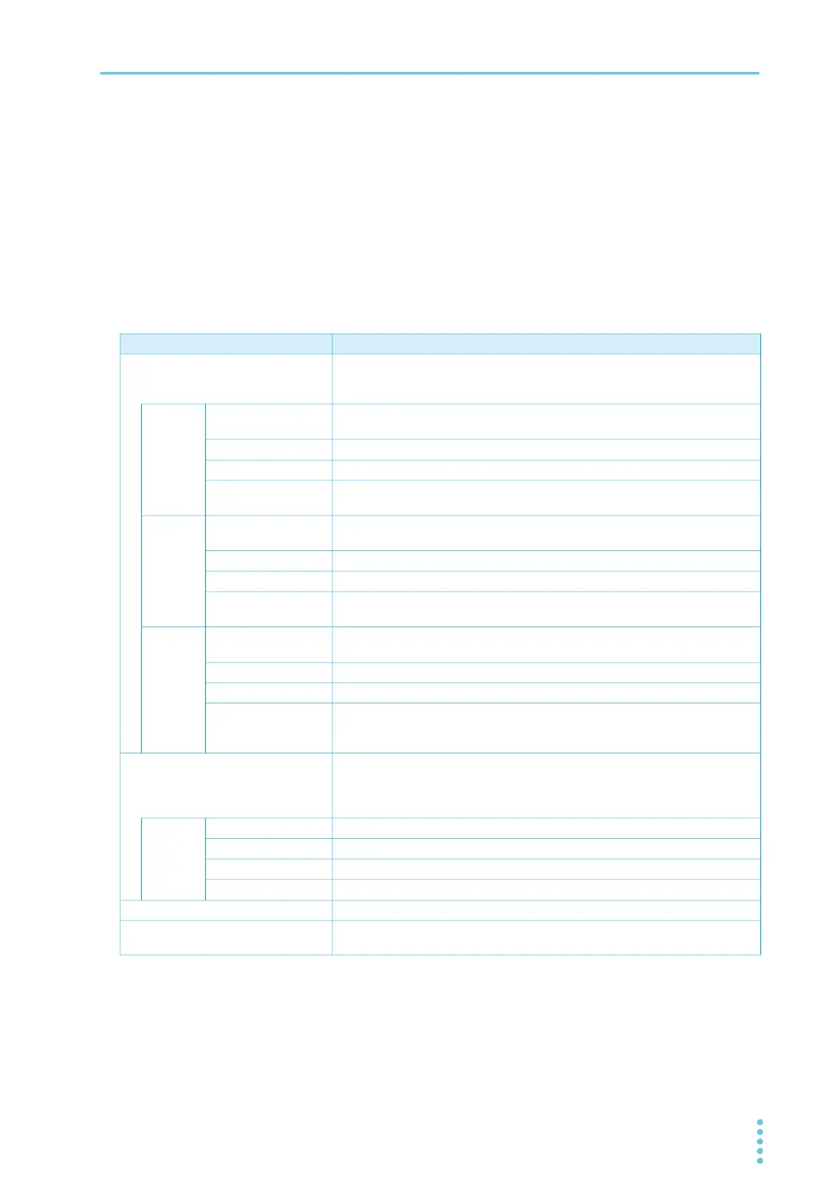
Item Specifications
Behavior based on judgment The output is shut off when a judgment is made. Buzzer volume level can be set
in the range of 0 (OFF) to 10 for pass and fail separately. In an auto test, the
buzzer is valid only for the judgment that takes place at the end of the program.
UPPER
FAIL
Judgment method UPPER FAIL results when a resistance greater than or equal to the Upper limit
is detected. Judgment is not made during or Voltage rise time.
Display “Upper-FAIL” is displayed.
Buzzer On
SIGNAL I/O The Upper-FAIL signal is generated continuously until a STOP signal is
received.
LOWER
FAIL
Judgment method LOWER FAIL results when a resistance less than or equal to the Lower limit is
detected. Judgment is not made during the judgment delay (Judge Delay).
Display “Lower-FAIL” is displayed.
Buzzer On
SIGNAL I/O The Lower-FAIL signal is generated continuously until a STOP signal is
received.
PASS Judgment method PASS judgment is made if Upper-FAIL or Lower-FAIL has not occurred when
the test time elapses.
Display “PASS” is displayed.
Buzzer On (fixed to 50 ms)
SIGNAL I/O The PASS signal is generated for the length of time specified by the Pass Hold
setting. If Pass Hold is set to Infinity, the PASS signal is generated continuously
until a STOP signal is received.
Voltage rise rate judgment operation Monitors the voltage rise rate during Voltage rise time. This is valid when Auto
setting of the judgment delay (Delay Auto) is set to on and the output voltage is
200 V or more. The output is shut off when a judgment is made. Buzzer volume
level can be set in the range of 0 (OFF) to 10 for pass and fail separately.
dV/dt
FAIL
Judgment method When the voltage rise rate (dV/dt) is less than approx. 1 V/s.
Display “Lower-FAIL (dV/dt)” is displayed.
Buzzer ON
SIGNAL I/O The L FAIL signals are generated continuously until a STOP signal is received.
Upper limit setting range 0.001 MΩ to 100.000 GΩ (in the range up to the maximum rated current), OFF
Lower limit setting range 0.000 MΩ to 99.999 GΩ (in the range up to the maximum rated current), OFF.
Setting 0.000 is equivalent to OFF.