TOS93 Series User’s Manual 85
Withstanding Voltage and Insulation Resistance Tests | Starting a Test
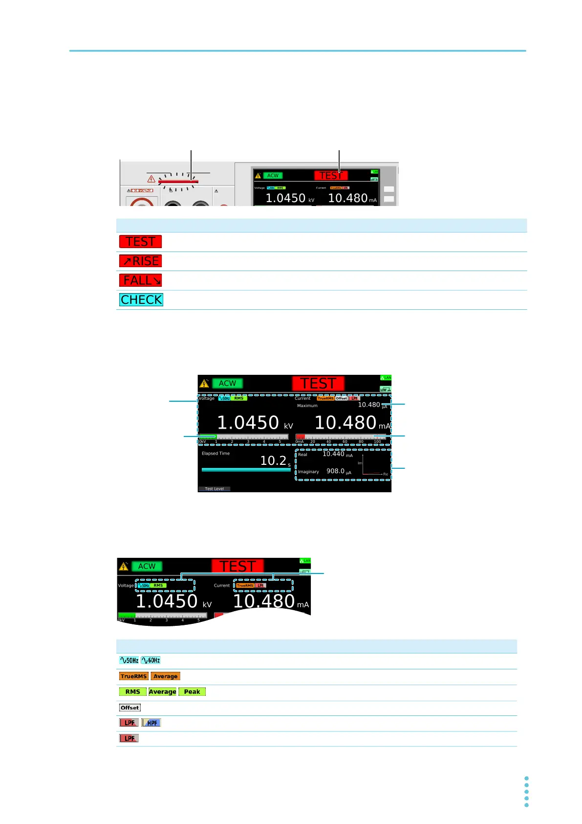
DANGER LED and test status display
During a test, the DANGER LED lights, and the test status is shown in the upper right of the display. The
DANGER LED lights if voltage remains at the output terminals regardless of the test status.
Measurement display
During a test, measurements are shown on the display.
Test condition display
Icons indicating the test conditions appearing during testing.
Test status Description
Testing
Voltage rising
Voltage falling
Performing Contact Check for scanner
Icon Description
/
Frequency setting (50 Hz/60 Hz).
/
Current RMS setting (TrueRMS/Average).
/ /
Volt Measure setting (RMS/Average/Peak).
Offsetting.
/
ACW or DCW test: Filter setting (LPF/HPF)
IR test: Low Pass Filter being set to ON.
OUTPUT
DANGER
110%
LEAKAGE
CURRENT
HIGH VOLTAGE
EARTH CONTINUITY
OUTPUT
LOW HIGH
Ratio of the output
voltage relative to
the Test Voltage
setting
Ratio of the measurement
relative to the Upper value
ACW: Shows the real and
imaginary phases
IR: Shows the measurement
When Display Peakhold is set to
ON, a peak value is displayed.