151
The internal I/O terminal of the XT3
Your XT3 features two potential free (dry contacts) inputs and one output.
The inputs allow you, just as the sensor input, to connect wired devices of other
manufacturer (e.g. existing door contacts, fingerprint, motion detectors, access control),
to your alarm panel. You can find these inputs if you open the alarm panel as described
in the chapter “Installation of the XT3”.
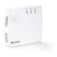
In the sensor list, the inputs are listed as “door contact (intern)” and the output as
“power switch (intern)”.
The output works similar to the output of the 12/24V relay. You can manually switch the
output via “Smarthome” “Wireless plugs” or via a home automation rule. You can
control (close) power circuits up to 24V/3A – do not exceed these values!
The internal door contacts and the power switch require always a connection of two
connectors to work properly.
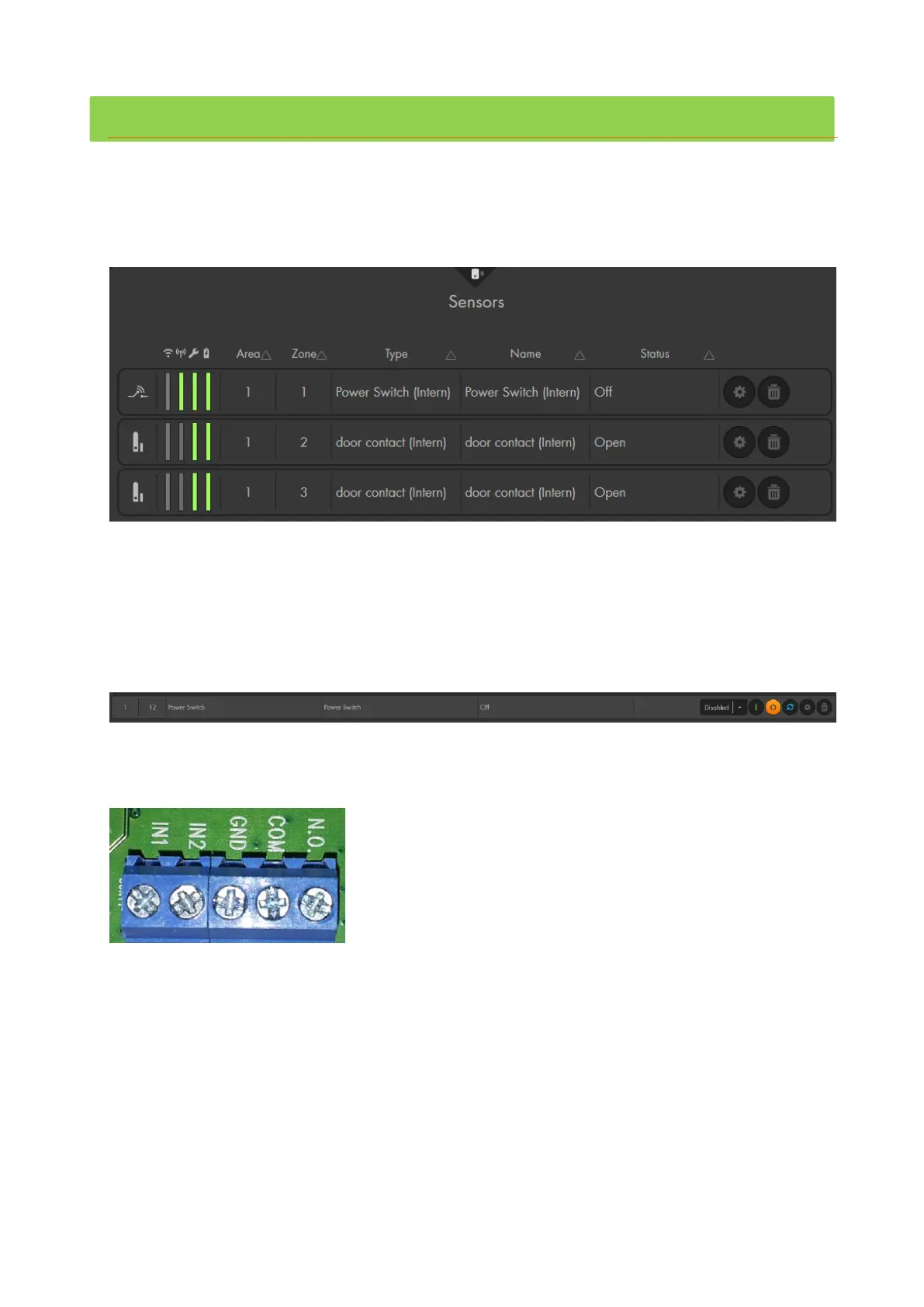
The connectors are the following (from left to right):
Inputs
o IN1:
Part of the first sensor input. By default it is “door contact” in zone 2 in the sensor
list. You need to connect one wire of your potential free alarm sensor to this
input. The second wire needs to be connected to GND.
o IN2:
Identical to IN1, this is the second sensor input. By default, it is listed as “door
contact” in zone 3 in the sensor list. As with the first input, you need to connect
one wire of your potential free sensor to this connector and the other wire to
GND.