156
12 / 24 V wireless relay
Attention:
This product is not compatible with the XT1 or XT2 without “Upgrade dongle to XT2
Plus.”
ATTENTION:
The installation may only be performed by a person who is trained, certified,
and has a profound knowledge about electronic devices and electrical
engineering
Product description:
The 12 / 24 V wireless relay can switch a potential-free contact similar to the wireless
relay (item no. 12014). The difference is that the wireless relay (12014) is only active in
case of alarms, whereas the 12 / 24 V wireless relay can also be activated manually, at a
certain time, or via the automation menu of the alarm panel.
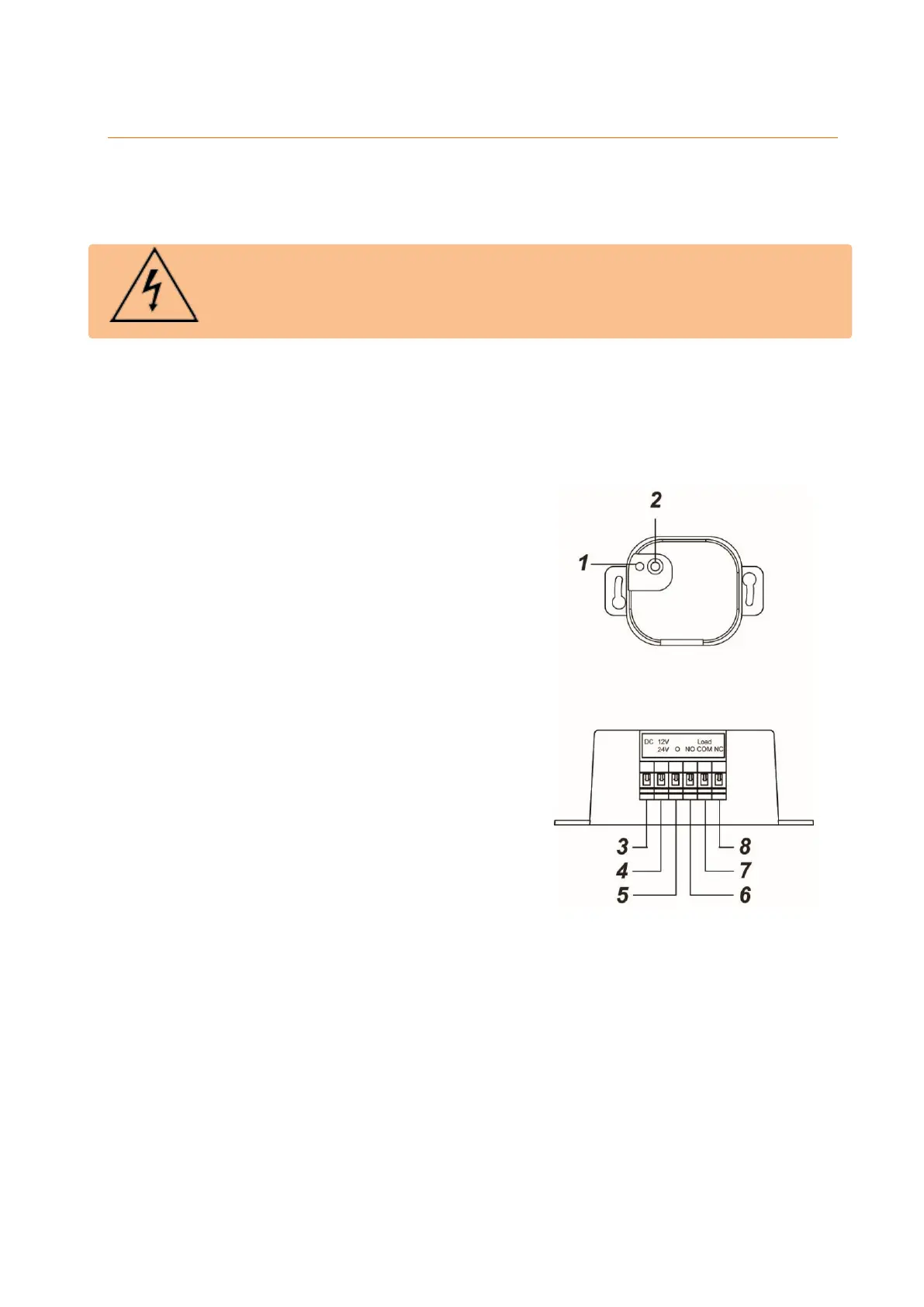
1. LED indicator
a. Flashes once: relay was reset
b. Flashes twice: relay connected to
alarm panel
c. Flashes once every 20 min: relay has
lost connection to the alarm panel or
network
2. Learn button
Pressing the learn button for more than ten
seconds resets the wireless relay and
deletes it from the sensor list. At the same
time, it sends a connection request to the
alarm panel.
3. Reserved
Do not use this connector!
4. 12 / 24 V DC input (+)
Phase conductor (brown – L)
5. 12 / 24 V DC-input (-)
Neutral conductor (blue – L)
6. NO (normally open)"
NO for normally open connection to the device
7. COM (changeover contact)
Phase conductor output
8. NC (normally closed)
NC for normally closed connection to the device