322
Wireless relay
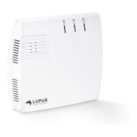
Product description:
1. Control LED
2. Function switches
3. Terminal clamps
4. 9V Jumper
5. Buzzer
Includes:
1 x 9V DC mains adapter
2 x screws and dowels
1 x attachment strip
1 x Manual
1 x wireless relay
Connecting the wireless relay and putting it into operation
1. Open the bottom of the wireless relay.
2. Connect the supplied power supply unit to the wireless relay.
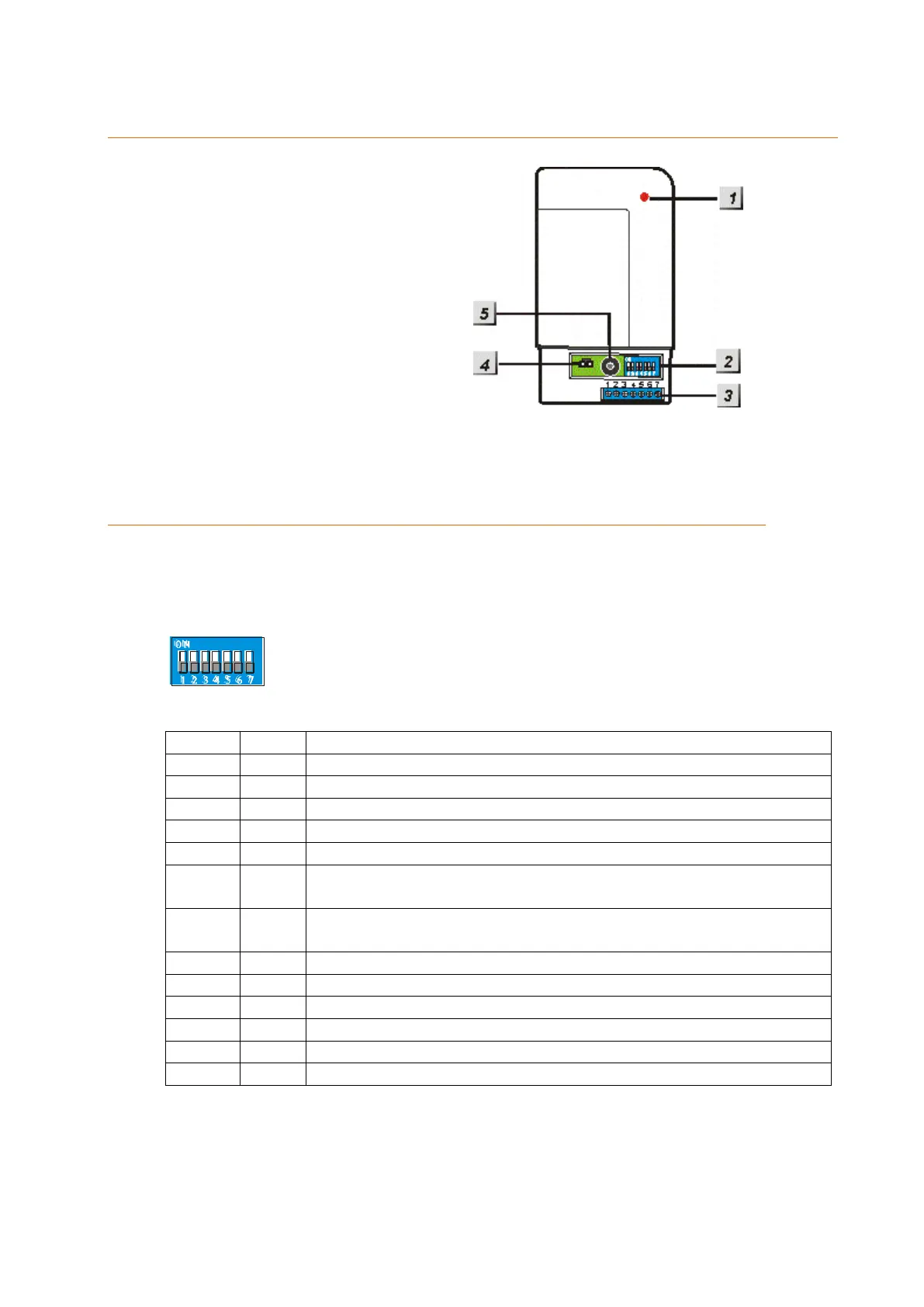
3. A blue switch bay with altogether seven switches is located on the right side. By
default, they are all set to OFF (down).
4. The following table lists the functions of the switches:
Allows you to add the relay to the alarm panel
Alarm switches relay ON until manually deactivated
Alarm switches relay ON for 3 minutes or until manually
deactivated
Arm mode switches relay ON / Disarm mode switches relay
OFF
Switching in case of an alarm
Perimeter alarm (burglar alarm)
Fire alarm switches relay ON
Water alarm switches relay ON
All acoustic alarms switch the relay on (not silent alarms)
5. To connect the wireless relay, set SW1 from OFF to ON. The control lamp of the
wireless relay lights up briefly as a confirmation.
6. Start the alarm panel’s configuration page, open the menu “Sensors” “Add”
“Add device” and specify the area to which you want to add the wireless relay.
Afterwards click on “Apply now”.