261
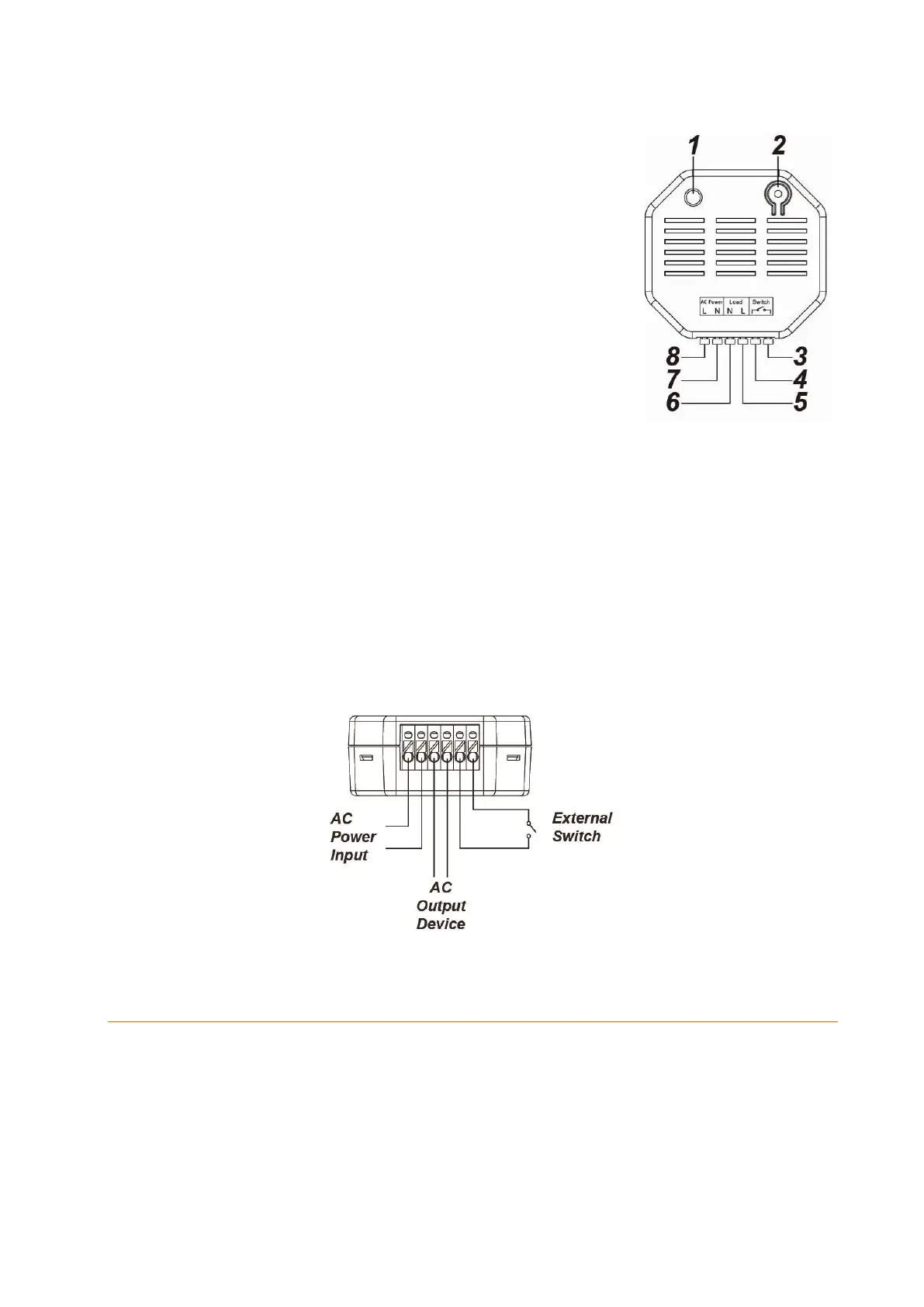
1. LED indicator
On: relay on
Off: relay off
Flashes twice: signal transmission
2. Learn button
Pressing the button briefly activates or deactivates
the relay.
Press the Learn button for ten seconds or longer to
reset the relay and send a learn signal to the control
unit.
3. Switch input 1
115V!
4. Switch input 2
115V!
5. 230V AC output (load)
Phase (brown - L)
6. 230V AC output (load)
Neutral conductor (blue - N)
7. 230V AC input (power)
Neutral conductor (blue - N)
8. 230V AC input (power)
Phase (brown - L)
Wiring diagram:
Connecting relay with power meter for XT2 Plus and putting it into operation
1. Deactivate the power supply during the installation to prevent short circuits.
2. Connect the 230 V supply line (power) to the input (7 + 8) and the 230 V end device
cable (load) to the output (5 + 6).
3. To control the relay externally, connect an additional potential-free switch to the
switch input (3 + 4).
4. You can add the relay with power meter to the alarm panel only within the first
three minutes after having connected it to the power grid!
5. Open the menu “Sensors” “Add” and press “Start” in the web interface of the