269
Flashes twice:
The scenario switch V2 was added successfully to the alarm panel.
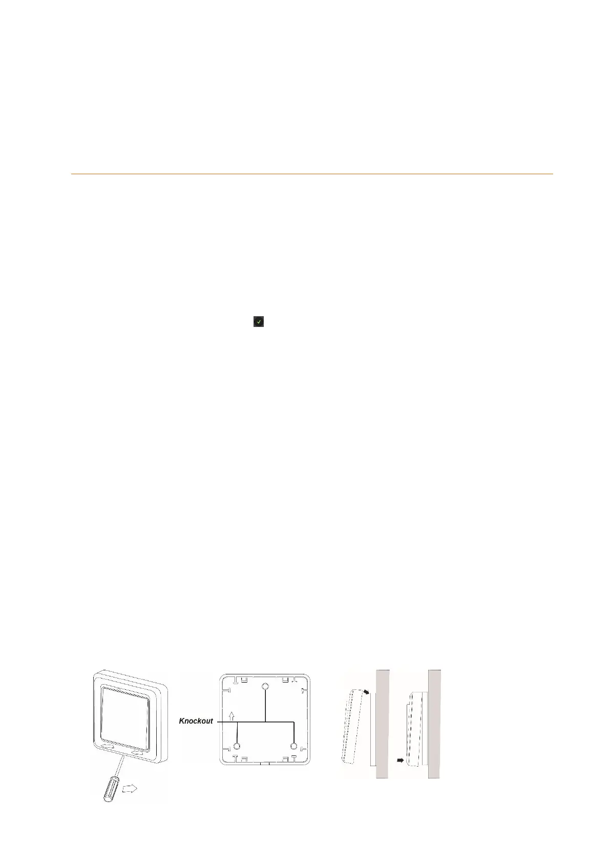
6. Installation notches
Connecting the scenario switch V2 and putting it into operation
1. Insert the batteries into the battery compartment of the scenario switch.
2. You can add the scenario switch V2 to the alarm panel only within the first three
minutes after having connected the scenario switch to the its power supply!
3. Open the menu “Sensors” “Add” and press “Start” in the web interface of the
alarm panel.
4. Press the learn button (4) for approx. ten seconds. The LED (6) lights up briefly.
Release the button afterwards.
5. If the alarm panel recognizes the scenario switch, the LED lights up twice briefly.
6. As soon as the alarm panel has received the connection request, the sensor list
shows the sensor. Press to add the scenario switch V2 to the alarm panel.
Assign an optional name.
Range test:
7. Open the alarm panel menu “Sensors” “Range” and press “Start.”
8. Press the learn button.
9. The sensor and the signal strength should be indicated. The higher the indicated
number the better the reception (1-9).
Please note:
If the signal strength at the place of installation is below 4, we advise to use a ZigBee
repeater, since it is normal that the signal strength may fluctuate for 2-3 points, thus,
a signal loss is possible.
Assembly
Install the scenario switch V2 on a flat surface.
1. Remove the front using a screwdriver.
2. Three notches are located on the back of the scenario switch V2. You can drill
through them to mark the drill holes at the wall.
3. Screw the back tight to the wall.
4. Click the front in place onto the fixed back.