160
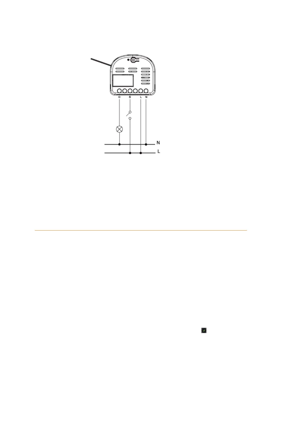
Wiring diagram:
Connect the single channel relay according to the following diagram:
You can use an external switch (see figure) to switch the single channel relay on
or off. It is not possible to use a push-button switch instead of a switch!
The inputs next to the external switch (S) are reserved and may not be used.
It is common to use wago connectors to connect the 230V neutral conductor input
and output (4 + 7).
Connecting the single channel relay and putting it into operation
1. Deactivate the power supply during the installation to prevent short circuits
2. Connect the 230V AC power supply with the 230V AC input (6 + 7) and the 230V AC
load to the 230V AC output (4 + 7). Refer to the figure above.
3. Reestablish the power supply.
4. You can only add the single channel relay to the alarm panel within the first three
minutes after the power supply was established.
5. Open the main menu of the alarm panel.
6. Open the menu “Sensors” “Add”.
7. Click “Start”.
8. Keep the learn button pressed for approx. ten seconds; the LED lights up briefly.
Release the learn button. The relay transmits the connection request and the LED
flashes twice.
9. The alarm panel will confirm the successful addition with a brief signal tone and
display the sensor in the menu “Sensors” ”Add”. Click on next to the listed sensor
to finish the connection process.
Range test:
1. Open the alarm panel menu “Sensors” “Range” and press “Start”.
2. Press the learn button.
3. The sensor and the signal strength should be indicated. The higher the indicated
number the better the reception (1-9).