16
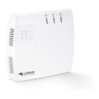
4. Connect the LAN cable to the alarm panel and then connect it to an internet router.
5. Mount the XT1 alarm panel to the wall mount. Make sure that the alarm panel locks
to the wall mount.
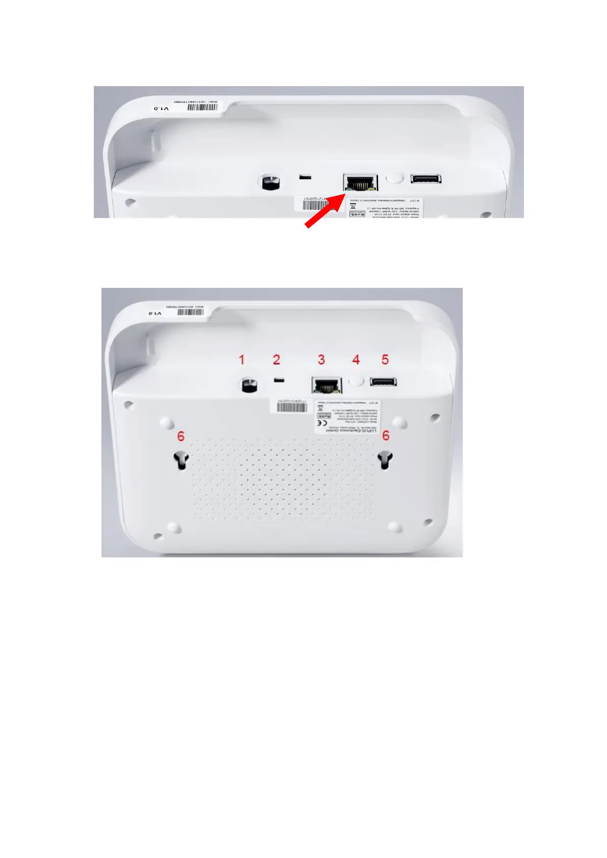
Description of the connectors:
1. Power supply connection
2. Battery on/off switch
On towards the power supply connector / off towards the LAN port
3. LAN port
4. Reset button
5. USB port
Currently no function
6. Mounting holes
For wall installation. The tampering contact of the alarm panel closes when the
alarm panel is locked onto the wall mount.