273
3. The sensor and the signal strength should be indicated. The higher the indicated
number the better the reception (1-9).
Please note:
If the signal strength at the place of installation is below 4, we advise to use a repeater,
since it is normal that the signal strength may fluctuate for 2-3 points, thus, a signal
loss is possible.
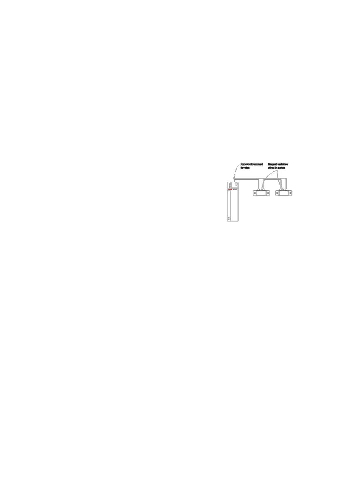
Example: How to connect a wireless sensor input to available wired detectors:
1. Open the housing of the sensor input.
2. The plastic material of the housing is thinner on top. This is where you can break
through to insert the cable in the housing.
3. Connect the cable to terminal 6 (CON4) of the sensor
input. Depending on the function (SW 6), set the
detector to either to “Normally open” or “Normally
closed.”
4. If the circuit is closed or opened (depending on
SW6 setting), this is reported to the alarm panel.
Note:
The maximum output resistance is 30 ohm.
If the battery of the sensor needs to be changed, we recommend removing the old
battery and discharging the residual voltage completely by pressing the learn
button repeatedly before the new battery is inserted.
You should follow the same procedure if the position NO/NC is changed by DIP
switch SW6. Only then the NO/NC function is changed (6).
The “SET/USNET” function allows you to immediately arm/disarm the alarm panel
irrespective of the set delay times. For more information see chapter “edit sensors”
in the manual of the XT.