275
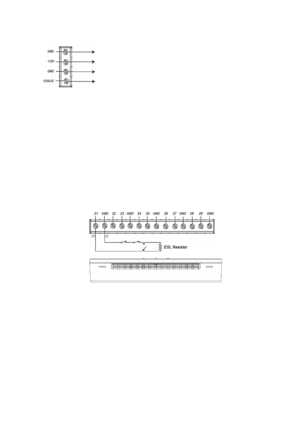
7. Power terminal
+12V / GND Input
12V AUX/GND Output
You can use the output to supply other devices with 12V.
The power output features 12V (100mA).
8. Backup battery connector
9. Drill holes
Power supply and battery:
Connect a 12V DC mains adapter to the power terminal. Connect the
positive conductor to (+12V) and negative cable to (GND). After you
have connected it correctly, the LEDs light up.
The sensor input (9 fold) charges the battery automatically if it is
connected with the grid.
In case of an interruption of the power supply via the mains adapter, a
signal is send to the alarm panel.
In case the battery is low, a signal is send to the alarm panel.
The power output features 12V (100mA).
Connectors:
1. Connect a wired sensor to the connectors. One cable connects to the input (Z1-
Z9), the other with GND.
2. It is required that a sensor is always connect to Z1. Otherwise, the sensor input
does not work properly.
3. Do not connect more than one sensor to each of the inputs (Z1-Z9). Hence, you
can connect maximal nine sensors to the sensor input (9 fold). Of course, you
can connect multiple sensors to one input, if the sensors are connected in series.
4. It is necessary to use the included ohmic resistance of 1k – 10K for every
connected sensor. Otherwise, the sensor input does not find the connected
sensor during the calibration process.
Install the ohmic resistance in the wiring to the sensor and as close to the
connected sensor as possible / as far away from the sensor input as possible).
5. To use NC (normally closed) inputs for Z1 to Z9, connect the ohmic resistance in
series.
6. To use NO (normally open) inputs for Z1 to Z9, connect the ohmic resistance in
parallel.