280
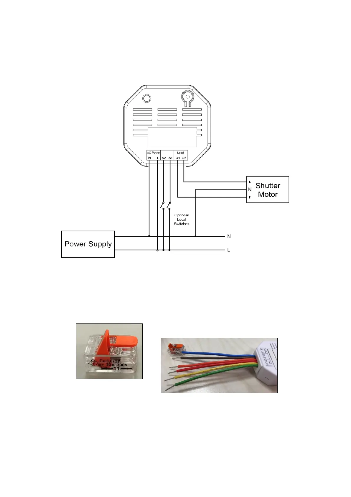
Wiring diagram:
Connect the neutral conductor (N) of the shutter relay V2 to the neutral conductor (N) of the power supply.
Connect the phase (L) of the shutter relay to the phase (L) of the power supply.
Connect O1 of the shutter relay to the up cable of the shutter motor (L).
Connect O2 of the shutter relay to the down cable of the shutter motor (L).
(Optional local push-button) Connect the push-button to the power supply and the up/down outputs of
the push-button to S1 (L) and S2 (L).
Perform the wiring according to this diagram
You can use the included Wago terminals 221 for cables between 0.2 and 4mm² (24
– 12AWG). You need to strip 11mm of the insulation for these terminals.
Open the lever to insert the
blue wire
into the opened Wago terminal.
Close the lever again and check that the Wago terminal is fixed.
Likewise, connect the neutral conductor (blue) of your power supply to the second
input of the Wago terminal. Make sure that there is no power on that wire!