214323 212 Revision B
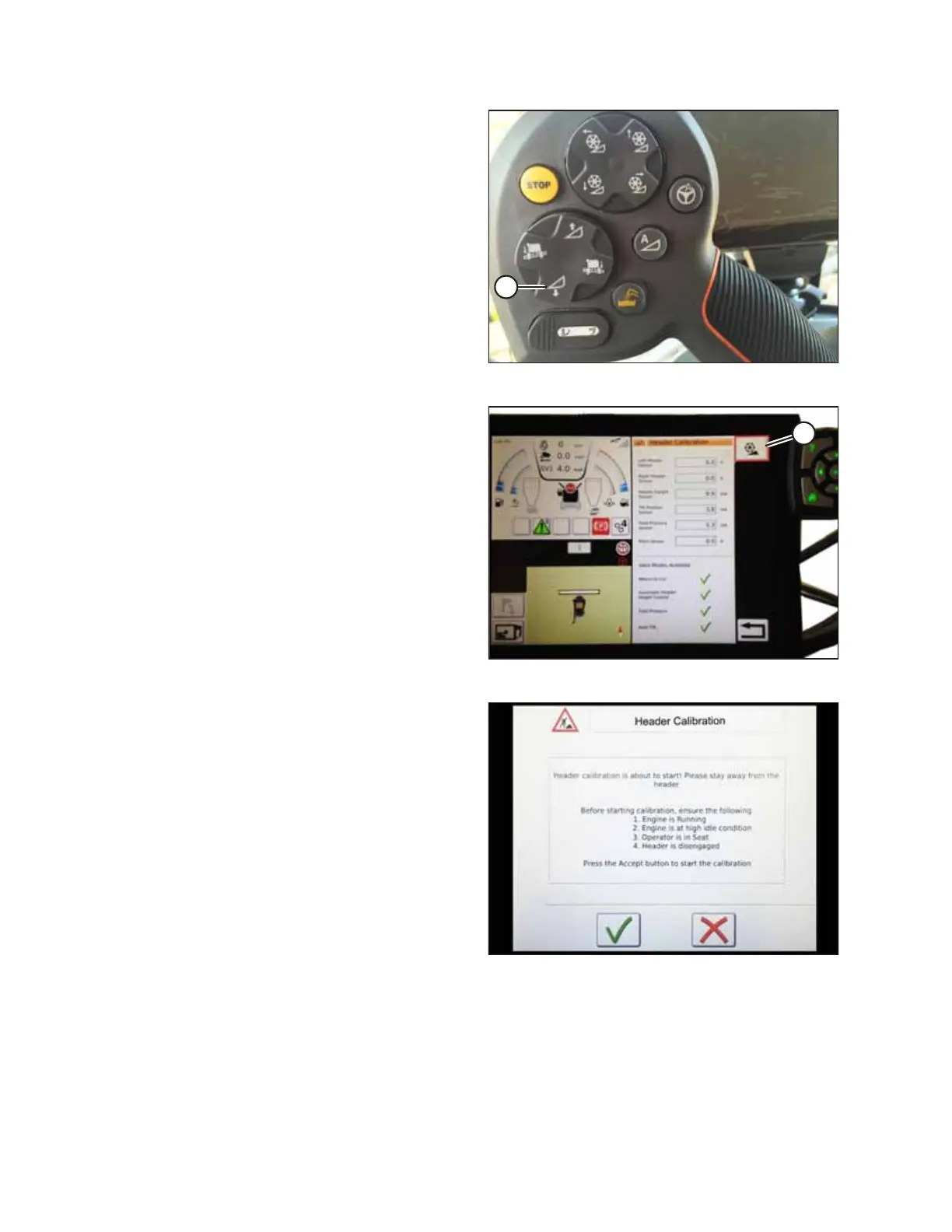
Figure 4.163: Header Down Switch
3. On the ground speed lever (GSL), press HEADER DOWN
button (A). The sensor values on the HEADER CALIBRATION
page will change as the header falls.
NOTE:
The header needs to be fully lowered and then fully raised.
The sensor voltage range should be between 0.7 and 4.3 V.
If the values do not fall within that range, the height
sensors will need to be adjusted. For instructions, refer to
4.4.2 Adjusting Voltage Limits, page 137
Figure 4.164: Header Calibration
4. Touch CALIBRATE icon (A).
Figure 4.165: Header Calibration Warning
5. The hazard message for the HEADER CALIBRATION
procedure will appear. Do NOT touch the green check mark
until all of the conditions listed on the page have been met.
6. Touch the green check mark to start the CALIBRATION
WIZARD.
AUTO HEADER HEIGHT CONTROL