MCM MODELS- BRAVO MODELS WITH DRIVE SHAFT EXTENSIONS - 2D-590-823225--1 1096
7. Position engine for correct engine and drive shaft
lateral alignment as follows:
a. Measure the length of (a) and (b) to the cen-
ters of bolt holes. They MUST BE EQUAL. If
they are not equal, slide the aft and forward
ends of the engine equal amounts in opposite
directions to obtain equal lengths for (a) and
(b).
b. Recheck Step 6. If Step 6 is not as specified,
adjust and recheck Step 7a. Continue this
process until both Steps 6 and 7a are as spe-
cified.
70246
These Dimensions Must Be Equal
b
a
8. After engine has been aligned correctly, fasten
front and rear engine mounts to stringers. Tighten
mounting bolts securely.
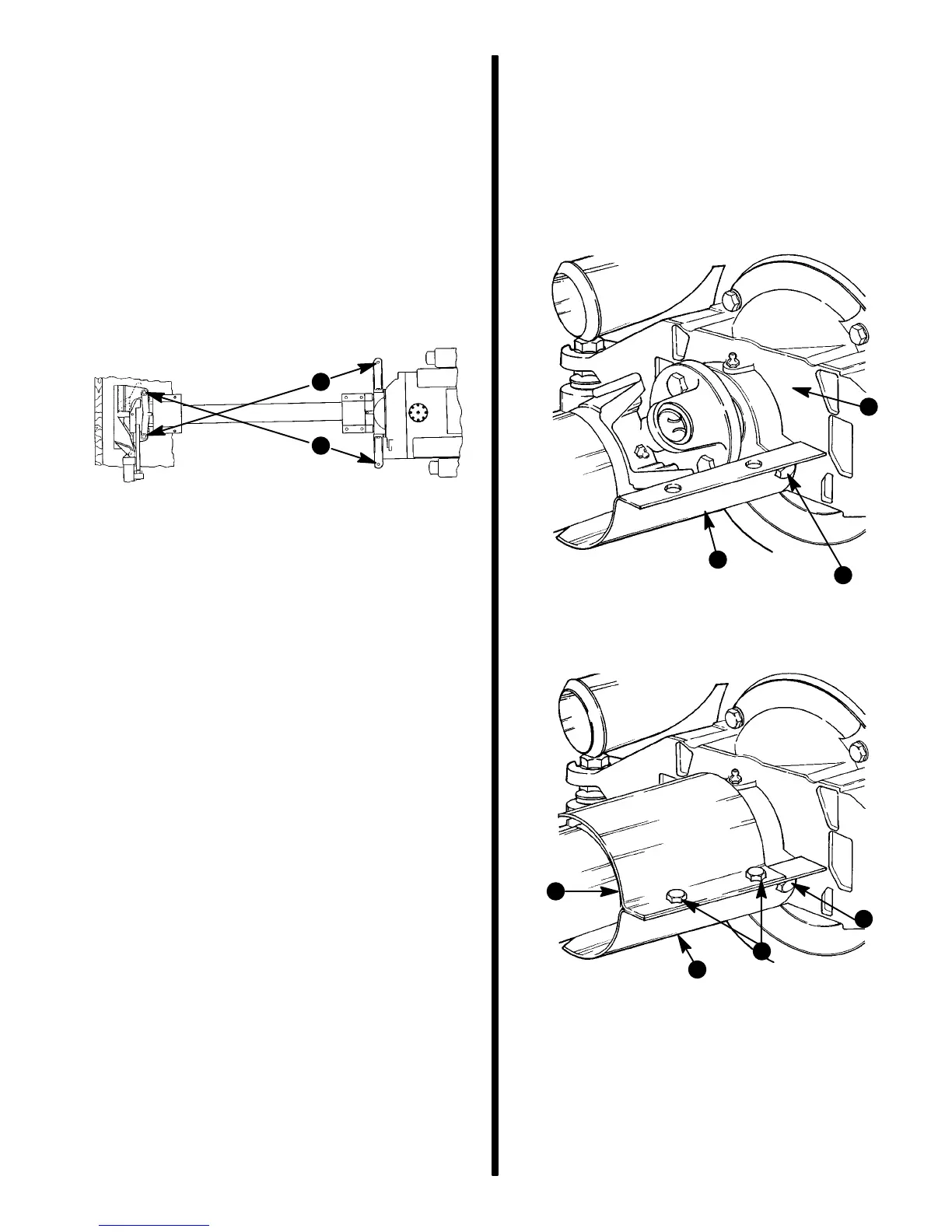
9. Apply Loctite 8831 to threads of bottom drive
shaft shield retaining screws and install bottom
shield on engine end as shown. Torque screws
to 30 lb. ft. (41 N·m). Then install top shield
as shown. Torque screws and nuts to 30 lb.
ft. (41 N·m).
72028
a - Shaft Housing
b - Bottom Shield
c - Screws (3 Used - Two Hidden in This View)
(Use Loctite 271)
Engine End Shown
b
c
a
72033
Engine End Shown
a - Top Shield
b - Bottom Shield
c - 4 Screws/Nuts (2 Hidden)
d - 3 Screws (2 Hidden)
b
c
d
a
10. Proceed to “Engine Connections” section in-
structions following.

 Loading...