90-823225--1 10965E-10 - ELECTRONIC FUEL INJECTION (MULTI-PORT AND THROTTLE BODY)
Electronic Control Module
(ECM) and Sensors
General Description
The MerCruiser Electronic Fuel Injection system is
equipped with a computer that provides the operator
with state-of-the-art control of fuel and spark delivery.
Computers use voltage to send and receive informa-
tion.
Computers and Voltage Signals
Voltage is electrical pressure. Voltage does not flow
in circuits. Instead, voltage causes current. Current
does the real work in electrical circuits. It is current,
the flow of electrically charged particles, that ener-
gizes solenoids, closes relays and lights lamps.
Besides causing currents in circuits, voltage can be
used as a signal. Voltage signals can send informa-
tion by changing levels, changing waveform (shape),
or changing the speed at which the signal switches
from one level to another. Computers use voltage
signals to communicate with one another. The differ-
ent sections inside computers also use voltage sig-
nals to communicate with each other.
There are two kinds of voltage signals, analog and
digital. Both of these are used in computer systems.
It’s important to understand the difference between
them and the different ways they are used.
Analog Signals
An analog signal is continuously variable. This
means that the signal can be any voltage within a cer-
tain range. An analog signal usually gives informa-
tion about a condition that changes continuously over
a certain range. For example, in a marine engine,
temperature is usually provided by an analog signal.
There are two general types of sensors that produce
analog signals: the 3-wire and the 2-wire sensor.
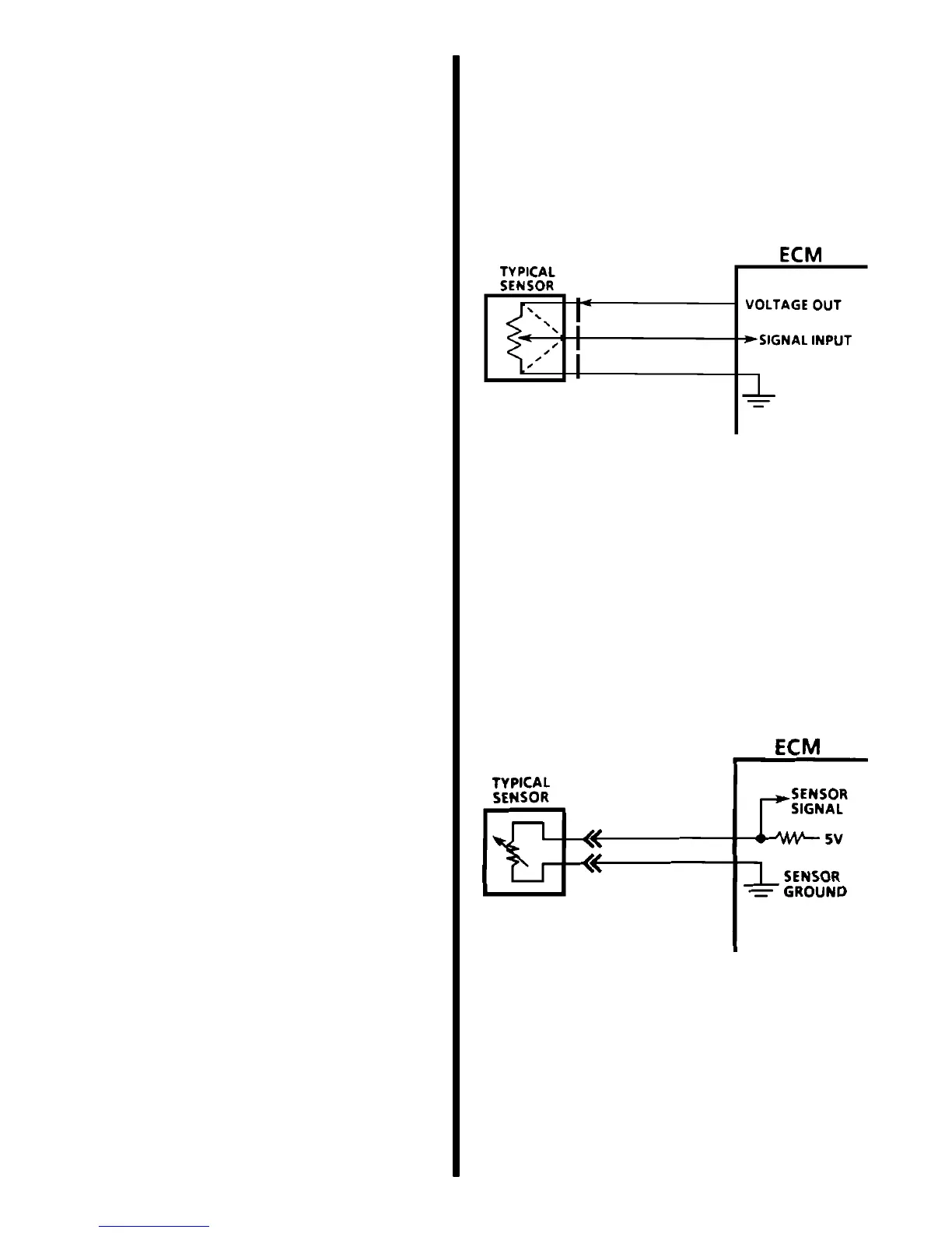
THREE-WIRE SENSORS (MAP AND TP)
The following figure shows a schematic representa-
tion of a 3-wire sensor. All 3-wire sensors have a ref-
erence voltage, a ground and a variable “wiper.” The
lead coming off of the wiper will be the signal to the
Engine Control Module (ECM). As this wiper position
changes, the signal voltage returned to the computer
also changes.
3-Wire Sensor
TWO-WIRE SENSORS (ECT AND IAT)
The following figure is the schematic of a 2-wire type
sensor. This sensor is basically a variable resistor in
series with a fixed-known resistor within the comput-
er. By knowing the values of the input voltage and the
voltage drop across the known resistor, the value of
the variable resistor can be determined. The variable
resistors that are commonly used are called thermis-
tors. A thermistor’s resistance varies inversely with
temperature.
2-Wire Sensor

 Loading...