ENGINES - 3A-3390-823225--1 1096
!
CAUTION
The head gasket may be holding cylinder head to
block. Use care when prying off cylinder heads.
DO NOT damage gasket surfaces. DO NOT drop
cylinder heads.
3. Place cylinder head on wooden blocks to prevent
damage to gasket surfaces.
Cleaning and Inspection
1. Clean gasket material and sealer from engine
block and cylinder heads.
2. Inspect sealing surfaces for deep nicks and
scratches.
3. Inspect for corrosion around cooling passages.
4. Clean head bolt threads and engine block bolt
hole threads, making sure no dirt, old oil or cool-
ant remain.
Installation
!
CAUTION
When using ribbed stainless steel head gaskets,
apply a thin coating of Quicksilver Perfect Seal to
both sides of gasket. Too much sealer may hold
gasket away from head or block causing leakage.
DO NOT use sealer on graphite composition
head gaskets.
1. Place head gasket in position over dowel pins.
2. Carefully set cylinder head in place over dowel
pins.
3. Coat threads of head bolts with Quicksilver Per-
fect Seal and install finger-tight.
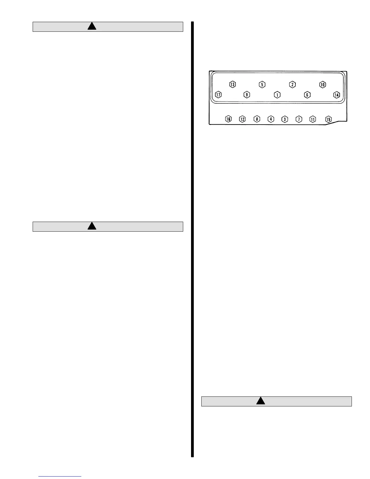
a. All Engines Except Gen+: Torque head
bolts in three steps, following torque se-
quence for each step. Start first step at 20 lb.
ft. (27 N·m), second step at 40 lb. ft. (54 N·m),
and finish with a final torque of 65 lb. ft. (88
N·m).
72332
b. Gen+ Engines Only: Torque cylinder heads
in two steps. Initial pass, torque all bolts to 22
lb. ft. (30 N·m). Second pass is an angle
torque sequence:
short bolts 55 degrees
medium bolts 65 degrees
long bolts 75 degrees
4. Install push rods and rocker arm assemblies in
their original positions. On roller cam engines
only, install baffle plate and retainers.
5. Adjust valves as outlined under “Valve Adjust-
ment - Engine Stopped.”
6. Install as outlined:
a. Intake manifold.
b. Rocker arm covers.
c. Exhaust manifolds.
d. Spark plugs.
e. Any components removed from front or rear
of cylinder heads.
7. Follow procedures in Section 6A or 6B of this
manual:
Seawater Cooled Models: Provide for adequate
water supply to seawater pickup (see Section
6A).
Closed Cooled Models: Refill closed cooling
section (see Section 6B), and provide adequate
water supply to seawater pickup.
!
CAUTION
Ensure that cooling water supply is available be-
fore starting the engine.
8. Start engine, set timing, set idle speed, and
check for leaks.

 Loading...