INSTRUMENTATION - 4D-190-823225--1 1096
Identification
NOTE: One of three distinct lines (Series) of Quicksil-
ver gauges may be installed (if equipped with Quick-
silver gauges). Aside from different gauge face ap-
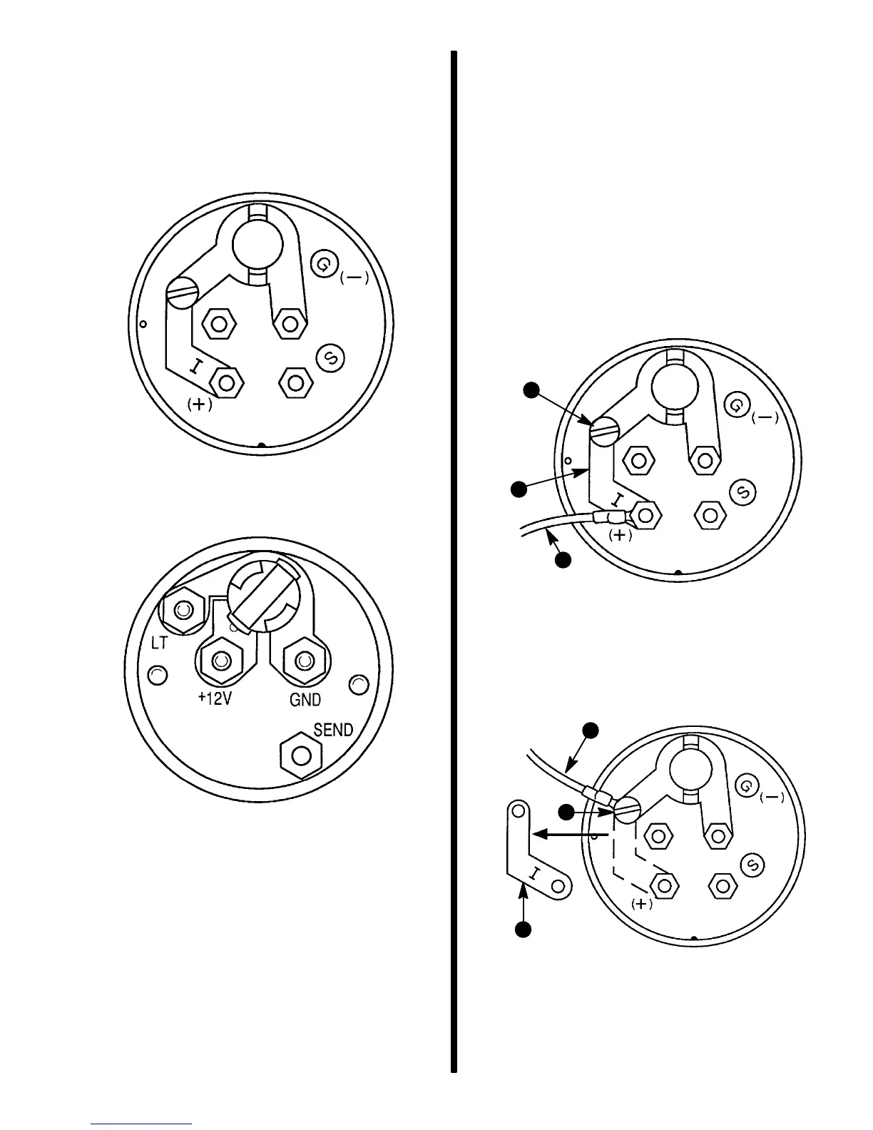
pearances and styling, the back of the gauges and
wiring connections are different as shown.
72746
Back of Commodore and International Series
Gauge - Typical
72965
Back of QSI Series Gauge - Typical
Special Information
Lighting Options
COMMODORE AND INTERNATIONAL SERIES
These gauges may be wired so that the illumination
lighting is provided from the ignition switch or a sepa-
rate instrumentation lighting switch.
By removing contact strip “I” from between + terminal
and the screw as shown following, and supplying a
separate +12 V power supply to the screw connec-
tion, illumination lights can be operated independent
of ignition switch.
72966
b
c
a
Ignition Switch Lighting Circuit
a - Positive (+) 12 Volt Power Supply From Ignition Switch
b - Contact Strip “I”
c - Screw Connection
72967
b
c
a
Separate Instrumentation Lighting Circuit Wiring
a - Positive (+) 12 Volt Power Supply From Ignition Switch
b - Contact Strip “I”
c - Screw Connection

 Loading...