7D-6 - COLLECTORS 90-823225--1 1096
Air Tube Routing
1. Route air tubing from air pump to silencer valve
cylinders. Do not route air tubing close to hot sur-
faces - excessive heat will damage air tubes.
72775
b
c
d
a
d
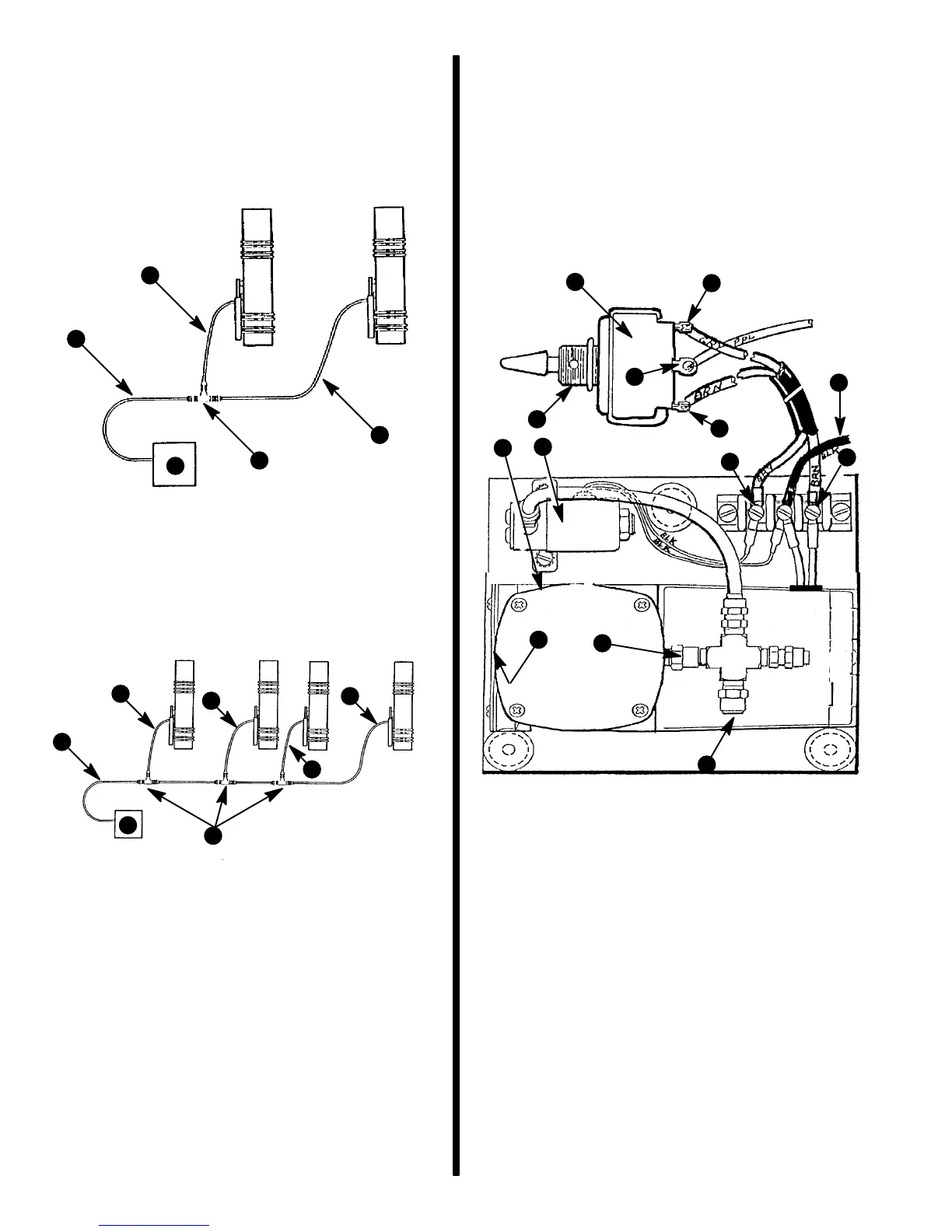
Single Engine
a - Air Tube
b - T-Fittings
c - Air Pump Assembly
d - Air Tube To Air Cylinder - On Each Silencer Valve
72776
b
c
d
a
d
d
d
Dual Engine
a - Air Tube
b - T-Fittings
c - Air Pump Assembly
d - Air Tube To Air Cylinder - On Each Silencer Valve
Maintenance
1. Air Intake Filter (32-17272) must be checked
once each year. If filter is clogged or partially
clogged, replace. The filter pad is glued in, and
may be removed with a needle-nose pliers.
Clean surface in casting, apply a single dot of
Quicksilver Sound Blanket Glue to center of cast-
ing, and install new filter. Be careful not to coat fil-
ter or clog air intake holes with adhesive.
72534
c
d
e
f
g
h
i
J
a
c
e
b
k
a - Mode Switch
b - Keyway - Install In DOWN Position
c - BROWN Wire To Terminal 3 - Activates Compressor
d - PURPLE Wire - 12 Volt; Connect To 12 Volt Source In
Control Panel Area
e - GRAY Wire To Terminal 1 - Activates Solenoid
f - Air Pump
g - Solenoid
h - Check Valve
i - Relief Valve - 30 PSI
j - 2 Ft. (610 mm) Ground Wire - Connect To Terminal 2 Must
Be Grounded To Engine
k - Air Intake Filter

 Loading...