VELVET DRIVE V-DRIVE AND WALTER V-DRIVE TRANSMISSIONS - 8B-790-823225--1 1096
Removal and Installation
NOTICE
The following procedure describes removal
of transmission without removing engine. If
engine must be removed, refer to Section 2
(see “Table of Contents”).
VELVET DRIVE TRANSMISSION ONLY
1. Drain transmission fluid.
2. Disconnect fluid cooler hoses.
3. Disconnect shift cable.
4. Disconnect wires from neutral start safety switch.
5. Disconnect wire from fluid temperature switch.
6. Disconnect propeller shaft coupling.
7. Remove four rear mount (to engine bed) bolts.
8. Support rear part of engine with either a hoist or
by using wooden blocks under flywheel housing.
9. Remove two center transmission-to-flywheel
housing attaching bolts and install two long
studs.
IMPORTANT: These two long studs will help sup-
port weight of transmission during removal and
installation.
10. Remove remaining transmission attaching bolts.
11. Pull transmission straight back and off engine.
12. Before installing transmission, check transmis-
sion pump indexing for correct rotation. Refer to
“Pump Indexing.”
13. Check transmission output shaft rolling torque.
See “Specifications.”
14. Apply Quicksilver Engine Coupler Spline Grease
to transmission input shaft splines and engine
drive plate splines.
15. If removed, install rear engine mounting brackets
(to transmission) as outlined in Section 3 (see
“Table of Contents”). Torque to 45 lb. ft. (61 N·m).
16. Align transmission splines with drive plate
splines.
17. Slide transmission into place and secure with
bolts.
18. Remove two long studs (installed in Step 9) and
install remaining two bolts. Torque all bolts to 50
lb. ft. (68 N·m).
19. Relieve hoist tension and fasten rear engine
mounts to engine bed. Tighten bolts securely.
20. Connect wires to neutral start safety switch.
21. Connect tan/blue wire to fluid temperature
switch.
22. Connect fluid cooler hoses to transmission.
23. Connect and adjust shift cable(s) as outlined in
Section 2E - “MIE Models - Velvet Drive Trans-
missions.”
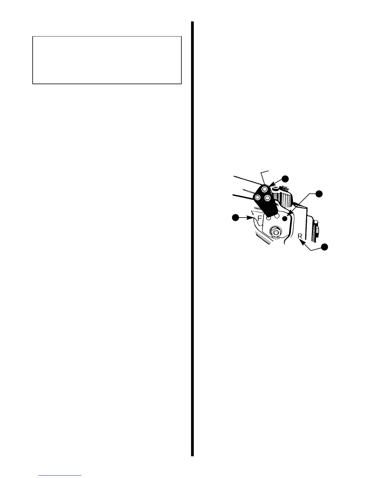
IMPORTANT: Velvet Drive Transmission Warran-
ty is jeopardized if the shift lever poppet ball or
spring is permanently removed, if the shift lever
is repositioned or changed in any manner, or if re-
mote control and shift cables do not position
shift lever exactly as shown.
72601
F – N – R
F
R
b
a
d
c
a - Transmission Shift Lever
b - Shift Lever Must Be Over This Letter When Propelling Boat
FORWARD
c - Shift Lever Must Be Over This Letter When Propelling Boat
REVERSE
d - Poppet Ball Must Be Centered In Detent Hole For Each
F-N-R position (Forward Gear Shown)
24. Refer to Section 2E - “MIE Models - Velvet Drive
Transmissions” and check engine final alignment
as outlined.
25. After engine has been properly aligned, connect
propeller shaft coupler to transmission output
flange. Attach couplers together with bolts, lock-
washers and nuts. Torque to 50 lb. ft. (68 N·m).
26. Refill transmission with specified fluid. Refer to
“Filling Transmission.”
27. Check for leaks and check fluid level after first en-
gine start-up.

 Loading...