ELECTRONIC FUEL INJECTION (MULTI-PORT AND THROTTLE BODY) - 5E-2790-823225--1 1096
ECM Connector and Symptom Charts
The following chart will aid in diagnosis of symptoms. These voltages were derived from a known good engine.
The voltages shown were done with the electrical system intact and operational. These are voltage requirements
to operate the different circuits.
!
CAUTION
Do not attempt to obtain these voltages by probing wires and connectors. Serious damage could result
in loss of engine operation or wiring damage. Voltages can vary with battery conditions.
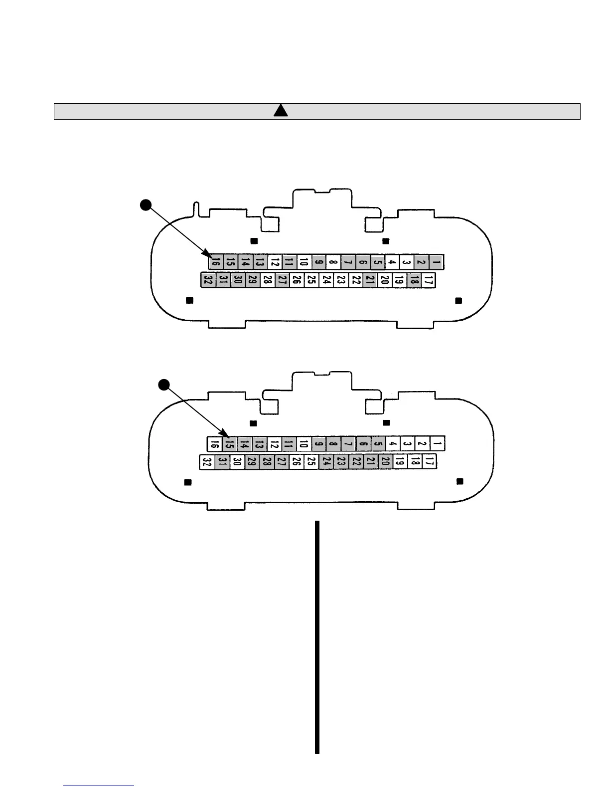
J-1
a
J-1 Front Pin 32 Pin Input Connector
J-2
a
J-2 Rear 32 Pin Output Connector
a - Shaded Area Denotes Pin Connector Location Used On
Terminal
NOTE: The Intake Air Temperature (IAT) Sensor
[J1-24], Port Fuel Jumper [J2-7 and J2-22] is not
used on the Throttle Body Injection system.
IMPORTANT: The following conditions must be
meet before testing.
1. Engine at operating temperature.
2. Ignition on or engine running.
3. Scan tool not connected.
THESE NOTES APPLY TO FOLLOWING ECM
CONNECTOR AND SYMPTOM CHARTS.
The “B+” Symbol indicates a system voltage (bat-
tery).
NOTE 1: Battery voltage for first two seconds, then
0 volts.
NOTE 2: Varies with temperature.
NOTE 3: Varies with manifold vacuum.
NOTE 4: Varies with throttle movement.
NOTE 5: Less than .5 volt (500 mV).
NOTE 6: Dual or multiple engines must share a com-
mon ground (–) for proper serial data communica-
tions.

 Loading...