4A-2 - STARTING SYSTEM 90-823225--1 1096
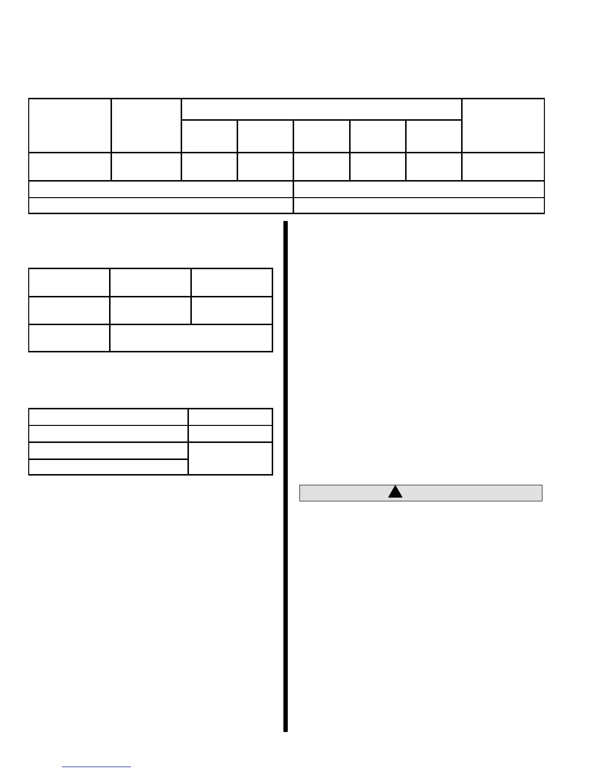
Direct Drive Starter Motor
Specifications
Delco
No Load Test
Brush
-
Identification
Number
Rotation
Volts
Min.
Amps
Max.
Amps
Min.
RPM
Max.
RPM
-
sion
Oz. (Grams)
10455602 LH 10.6 70 120 5400 10800
56-105
(1588-2976)
Pinion Clearance .010-.140 (0.25-3.5 mm)
Commutator End Frame Gap .025 Max. (0.6 mm Max.)
Torque Specifications
Fastener
Location
Lb. Ft. N·m
Starter Motor
To Block
50 68
All Other
Fasteners
Tighten Securely
Lubricants/Sealants
Description Part Number
Quicksilver Liquid Neoprene 92-25711-2
SAE 10W Oil
SAE 20W Oil
Positive Current Flow
This is a general description of the positive current
flow, from the battery and through the system until the
starter motor cranks.
• Battery to the solenoid switch (on starter)
(RED battery cable).
• Solenoid switch to circuit breaker (RED).
• Circuit breaker to wire junction (RED-PUR).
• Wire junction to wiring harness plug
(RED-PUR) terminal 6.
• Wiring harness plug to 20 amp fuse
(RED-PUR).
• 20 amp fuse to ignition switch terminal I
(RED-PUR). At this point ignition switch is
turned to START.
• Ignition switch terminal B to terminal S.
• Ignition switch terminal S to neutral start
switch (YEL-RED). NEUTRAL START SWITCH
MUST BE AT NEUTRAL POSITION.
• Neutral start switch to wiring harness plug
terminal 7 (YEL-RED).
• Wiring harness plug to starter solenoid (small
terminal) (YEL-RED). Also ensure that black
(small terminal) wire is grounded.
• Starter solenoid is now “closed,” completing
circuit between large terminal (RED-PUR) and
other large terminal (YEL-RED), causing
starter motor to crank.
!
CAUTION
The starter motor is designed to operate under
great overload and produce a high horsepower
for its size. It can do this only for a short time,
since considerable heat accumulates and can
cause serious damage. For this reason, the
cranking motor must never be used for more than
30 seconds at any one time. Cranking should not
be repeated without a pause of at least 2 minutes
to permit the heat to escape.

 Loading...