MIE MODELS - HURTH TRANSMISSION - 2F-390-823225--1 1096
11. Remove front and rear engine mounting bolts.
Retain hardware.
72638
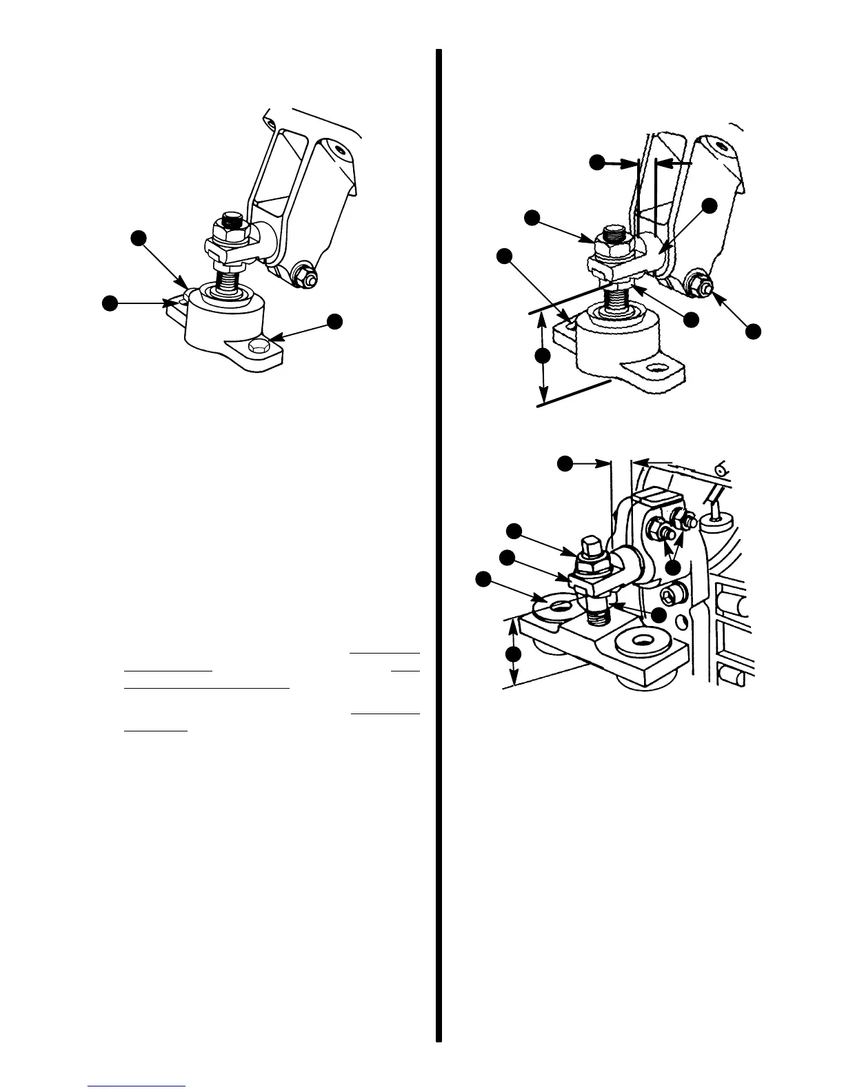
a - Bolts or Lag Screws (with Washers)
b - Slot Forward
b
a
a
12. Carefully remove engine.
Installation
Engine Installation and Initial
Alignment
1. Follow instructions “a” or “b”:
a. Engine mount(s) or adjustment WAS NOT
DISTURBED during engine service: Pro-
ceed to following Step 2.
b. Engine mount(s) or adjustment WAS DIS-
TURBED during engine service:
IMPORTANT: Engine mounts must be adjusted,
as explained in the following, to center mount ad-
justment and establish a uniform height on all
mounts.
Ensure that all mounts are:
(1) In the center of their up-and-down adjust-
ment.
(2) Mounting hole, which is a slot, is forward
(if so designed; new style is not slotted).
(3) Large diameter of mount trunnion ex-
tended as shown.
(4) Each mount base is downward. Tighten
clamping screws and nuts slightly to pre-
vent moving in or out. Mounts must be
free to pivot when installing engine.
f
a
b
c
d
e
g
f
a
b
c
e
d
7014
70158
Rear Mount - Typical
Front Mount - Typical
a - Locking Nut
b - Adjusting Nut
c - Trunnion Clamp Screw and Nut, with Lockwasher
d - Slot Forward (If So Designed)
e - 3/8 In.
± 1/16 In. (10 mm ± 2 mm)
f - 2-5/8 In.
± 1/16 In. (67 mm ± 2 mm)
g - Mount Trunnion
g

 Loading...