Reconnect WHT/RED
bullet connectors.
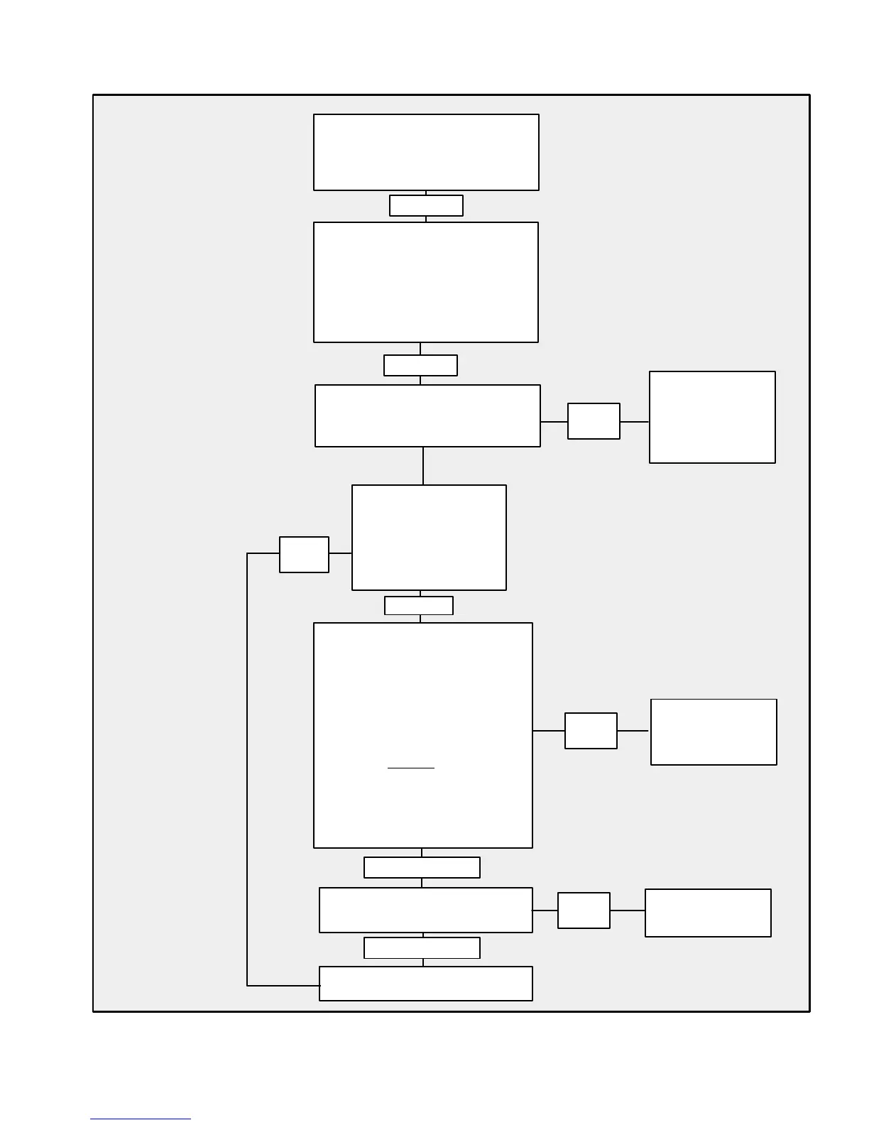
Remove High-Tension Lead
from Distributor to Coil. Insert
a Spark Gap Tester from Coil
Tower to Ground. Disconnect
WHT/GRN Lead from Distribu-
tor. Place Ignition Key in RUN
Position. Rapidly
strike the Ter-
minal of the WHT/GRN Lead
that comes from module,
against Ground (–).
(See “IMPORTANT” below)
12 Volts
IMPORTANT: The WHT/GRN lead must be touched against ground (–) 2-3 times per second
to simulate a running engine. Repeat this test several times to ensure that spark is present.
Replace Ignition
Sensor in
Distributor
Install New
Ignition Coil
Check Engine
and Instrument
Wiring Harness,
Battery Cables,
Key Switch
With Key in RUN Position,
Check for 12 Volts at Positive
(+) Terminal on Ignition Coil
Unplug WHT/
RED bullet connector
from Distributor.
Check for 12 volts
on lead coming
from module.
Substitute a New Ignition
Coil. Repeat Above Test
Replace Ignition Module
Check all Terminal Connections
at Distributor, Ignition Module
and Ignition Coil.
Battery OK?
Distributor Clamping Screw
Tight?
Check to ensure that tachometer
GRY lead is not shorted to
ground (–) at the tachometer or
within the harness.
0
Volts
0
Volts
Spark
at Coil
Spark
at Coil
No Spark at Coil
No Spark at Coil
No Spark
No Spark
12 Volts
TROUBLESHOOTING - 1C-990-823225--1 1096
Testing Thunderbolt V Ignition System

 Loading...