3A-32 - ENGINES 90-823225--1 1096
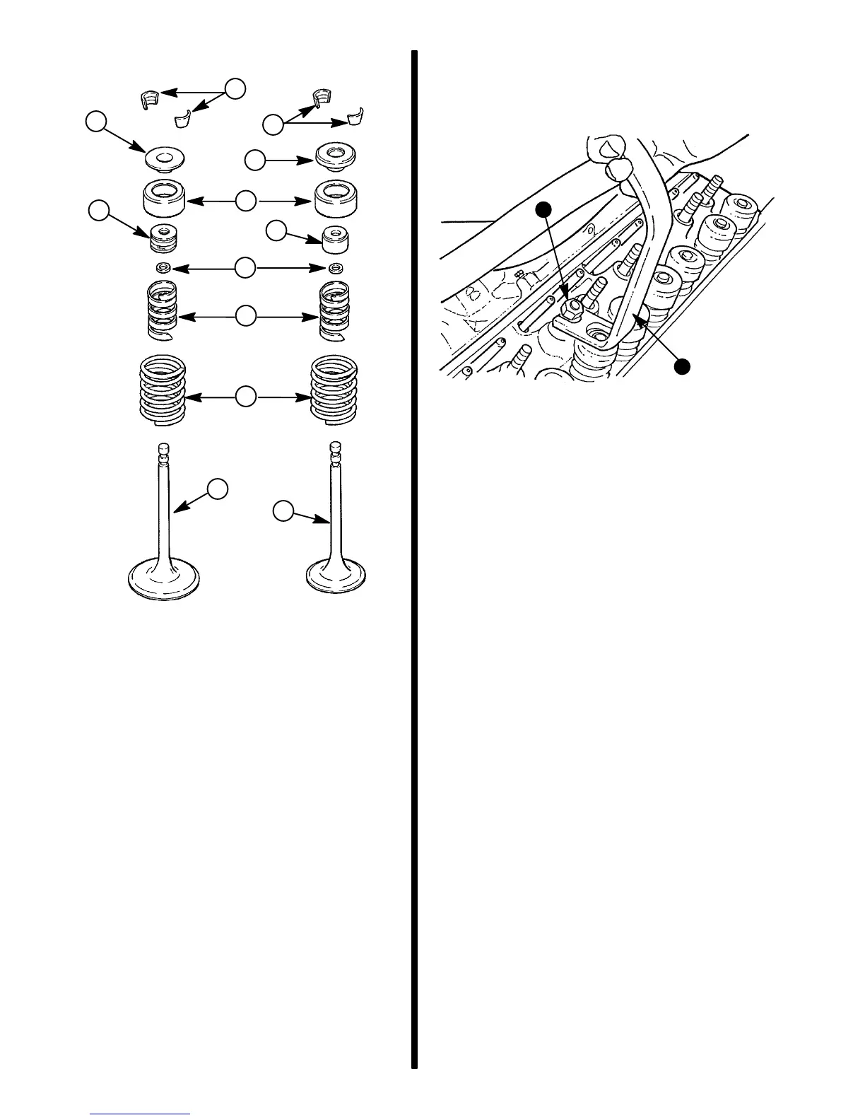
Valve Assembly (Exploded View)
72331
1 - Valve Locks
2 - Retainer
3 - Rotator
4 - Cap
5 - Valve Guide Oil Seal
6 - Oil Shield
7 - Valve Stem Oil Seal
8 - Inner Spring
9 - Outer Spring
10 -Intake Valve
11-Exhaust Valve
1
2
3
6
8
9
10
1
5
7
4
11
Installation - Head Installed
1. Install valve guide seal (intake valve only) over
valve stem and push down until seated against
head.
2. Set valve spring (with damper installed) and
shield in place.
3. Place cap on intake valve and/or rotator on ex-
haust valve.
4. While compressing valve spring with valve spring
compressor, install oil seal in lower groove of
valve stem, making sure seal is not twisted. A
light coating of oil will help prevent twisting.
5. Install valve locks (Quicksilver Needle Bearing
Assembly Lubricant may be used to hold them in
place) and slowly release tool, making sure locks
seat properly in upper grooves of valve stem.
72306
b
a
a - Valve Spring Compressor (J-%892)
b - Rocker Arm Nut
6. Install push rods and rocker arm assemblies.
7. Adjust valves as outlined under “Valve Adjust-
ment - Engine Stopped.”
8. Install rocker arm cover [torque to 90 lb. in.
(10 N·m)] and spark plug [torque to 15 lb. ft.
(20 N·m)].
Cylinder Head
Removal
1. Drain engine cooling system.
2. Remove as outlined:
a. Exhaust manifolds.
b. Intake manifold.
c. Rocker arm covers.
d. Rocker arm assemblies and push rods (keep
in order for reassembly in their original loca-
tions).
e. Any components attached to front or rear of
cylinder head.
f. Spark plugs.
g. Head bolts.

 Loading...