2F-4 –MIE MODELS - HURTH TRANSMISSION 90-823225--1 1096
!
CAUTION
Center lifting eye (located on top of thermostat
housing) is used for engine alignment only. DO
NOT use to lift entire engine.
!
CAUTION
DO NOT allow lifting sling to hook or compress
engine components or damage to them will oc-
cur.
2. Attach a suitable sling to lifting eyes on engine.
(Refer to “Removal” section for location of
lifting eyes.)
IMPORTANT: Engine bed must position engine
so that a minimum of 1/4 in. (6 mm) up-and-down
adjustment still exists on all four mounts after
performing final alignment. This is necessary to
allow for final engine alignment.
3. Lift engine into boat and position on engine bed
so that transmission output flange and propeller
shaft coupler are visibly aligned (no gap can be
seen between coupling faces when butted to-
gether). Adjust engine bed height, if necessary,
to obtain proper alignment. DO NOT use mount
adjustments to adjust engine position at this time.
72596
a
b
c
a - Propeller Shaft
b - Propeller Shaft Coupler
c - Transmission Output Flange
4. Check all four mounts to ensure that they are still
positioned properly, then fasten mounts to en-
gine bed with appropriate bolts or lag screws and
hardware. Tighten lag bolts/screws securely.
5. Disconnect and remove sling. Proceed to “En-
gine Final Alignment” section following.
Engine Final Alignment
!
CAUTION
To avoid vibration, noise and damage to trans-
mission output shaft oil seal and bearings, en-
gine must be properly aligned.
IMPORTANT: Engine alignment MUST BE RE-
CHECKED with boat in the water, fuel tanks filled
and with a normal load on board.
Engine must be aligned so that transmission output
flange and propeller shaft coupler centerlines are
aligned and coupling faces are parallel within .003 in.
(0.07mm). This applies to installations with solid cou-
plings, as well as flexible couplings.
1. Check mating surfaces on transmission output
flange and propeller shaft coupler faces to make
sure they are clean and flat.
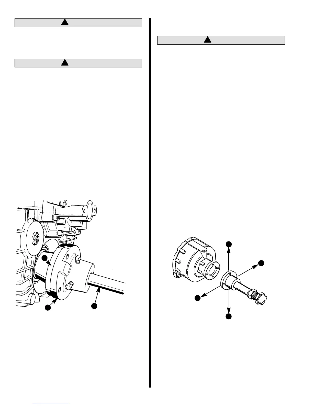
2. Center propeller shaft in shaft log as follows:
a. Push down and then lift shaft as far as it will
move. Then place shaft in the middle of the
movement.
b. Move shaft to port and then to starboard as
far as shaft will move. Then place shaft in the
middle of the movement.
c. With shaft in center of shaft log, as deter-
mined by above procedures “a” and “b,” align
engine to shaft.
a-Up
b - Down
c - Port
d - Starboard
72595
b
c
d
a

 Loading...