4A-38 - STARTING SYSTEM 90-823225--1 1096
Clearances
PINION CLEARANCE
Pinion clearance must be checked after reassembly
of starter motor.
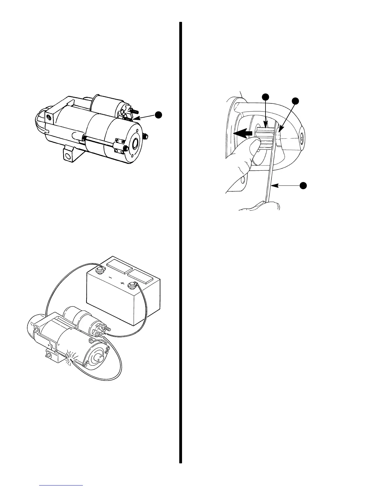
1. Disconnect brush lead from solenoid motor and
insulate it carefully.
74041
a
a - Brush Lead
2. Connect 12 volt battery positive (+) lead to bat-
tery terminal and negative (–) lead to frame.
3. Momentarily touch a jumper lead from battery ter-
minal to switch terminal. This shifts pinion into
cranking position where it will remain until battery
is disconnected.
72629
4. Push pinion back toward commutator end to
eliminate slack.
5. Measure distance between pinion and pinion
retainer.
6. If clearance is not within limits of .010-.160 in.
(0.25-4.00 mm), it may indicate excessive wear
of solenoid linkage, shift lever yoke, or improper
assembly of shift lever mechanism. Replace
worn or defective parts, since no provision is
made for adjusting pinion clearance.
72077
b
c
a
a - Pinion
b - Retainer
c - Feeler Gauge
Installation
IMPORTANT: Install special mounting shim (if
equipped) between starter motor and engine
block.
1. Place starter motor in position and install mount-
ing bolts. Torque bolts to 30 lb. ft. (41 N·m).
2. Connect YELLOW/RED wire to terminal S of so-
lenoid. Connect ORANGE wire, RED wire, and
battery cable to large terminal of solenoid. Tight-
en fasteners securely. Coat terminals with Quick-
silver Liquid Neoprene. Install battery cable boot,
if so equipped.
3. Connect battery cables to battery in the following
order. Connect positive (+) cable to positive (+)
battery terminal and tighten cable clamp. Then
connect negative (–) cable to negative (–) termi-
nal and tighten clamp.

 Loading...