2D-4 – MCM MODELS - BRAVO MODELS WITH DRIVE SHAFT EXTENSIONS 90-823225--1 1096
Installation
Engine Installation/Alignment
ENGINE MOUNT ADJUSTMENT WAS NOT
DISTURBED DURING SERVICE
!
CAUTION
Center lifting eye (located on top of thermostat
housing) is used for engine alignment only. DO
NOT use to lift entire engine.
!
CAUTION
DO NOT allow lifting sling to hook or compress
engine components or damage to them will oc-
cur.
1. Attach a suitable sling to lifting eyes on engine
and adjust so that engine is level when sus-
pended. (Refer to “Removal” section for loca-
tion of lifting eyes.)
2. Lift engine into approximate position (in boat),
using an overhead hoist.
3. Set engine on stringers.
4. Grease drive shaft universal joints with Quicksil-
ver 2-4-C Marine Lubricant.
!
CAUTION
When attaching shaft in next step, BE SURE that
the pilot on drive shaft flanges are engaged in in-
put shaft and output shaft flanges. Flanges
MUST BE flush to each other prior to tightening
screws or screws may come loose during opera-
tion.
!
CAUTION
Failure to align shaft flanges with matching
marks made on disassembly may cause improp-
erly aligned drive unit and extension drive shaft
U-joint centerlines resulting in a severe vibration
problem.
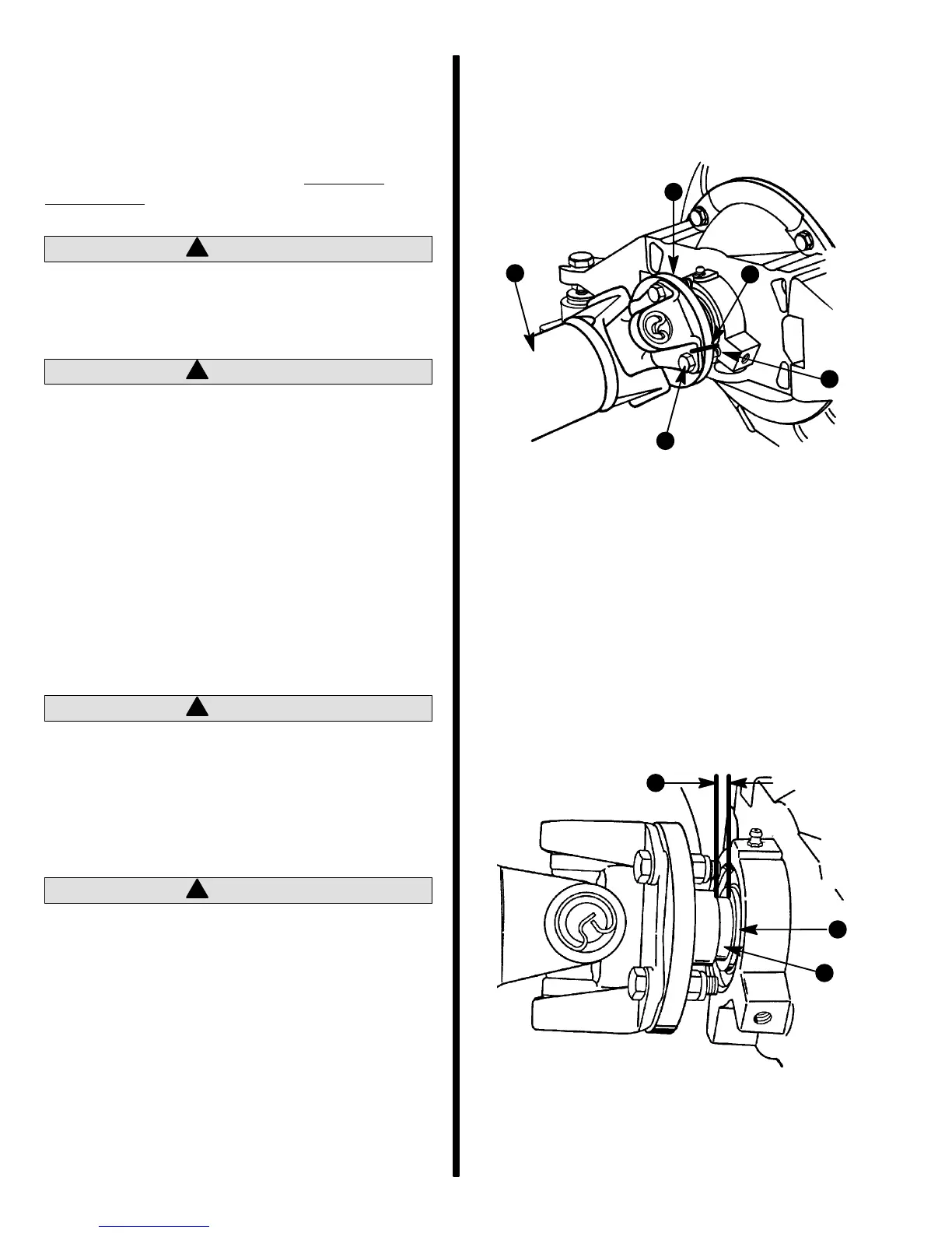
5. As shown, attach engine output flange to drive
shaft flange exactly as marked during disassem-
bly. Torque fasteners to 50 lb. ft. (68 N·m).
70237
b
c
d
a
e
Engine End Shown
a - Output Shaft Flange
b - Drive Shaft
c - Screw
d - Nut
e - Matching Marks Made Upon Disassembly - Aligned
IMPORTANT: Failure to properly position output
shaft flange may result in bearing damage.
6. Relieve hoist tension from engine, then slide en-
gine fore or aft as needed to obtain 1/4 in. (6 mm)
clearance between flange shoulder and exten-
sion shaft housing bearing.
72591
a - Flange Shoulder
b - Bearing
c - 1/4 In. (6 mm)
b
c
a

 Loading...