4B-18 - THUNDERBOLT IV AND V IGNITION SYSTEM 90-823225--1 1096
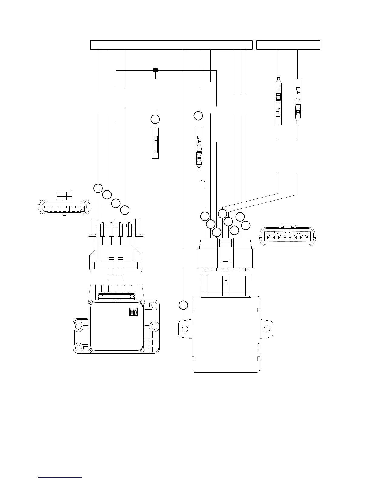
Ignition System Wiring Diagram
16 GRY
16 BLK
16 PUR
16 BLK
16 PUR
16 BLK
16 BLU
16 WHT/GRN
16 WHT/RED
1
2
3
4
5
8
9
10
11
3
7
16 PUR/WHT
13
TO DISTRIBUTOR
CBADE
16 PUR/WHT
16 PUR/WHT
IGNITION
CONTROL
MODULE
KNOCK
CONTROL
MODULE
16 BLK
TO ENGINE HARNESS
16 TAN/BLU
5
6
16 BLK
12
BLK = BLACK
BLU = BLUE
BRN = BROWN
GRY = GRAY
GRN = GREEN
ORN = ORANGE
PNK = PINK
PUR = PURPLE
RED = RED
TAN = TAN
WHT = WHITE
YEL = YELLOW
LIT = LIGHT
DRK = DARK
1 - Knock Sensor Wire
2 - Ground Wire (–) For Knock Module
3 - Knock Module Signal Wire
4 - Battery (+) Positive Wire To Knock Module
5 - Ground (–) For Future Options
6 - Audio Warning System Wire
7 - Distributor Wire
8 - Distributor Wire
9 - Battery (+) Positive Wire To Ignition Module
10- Ground Wire For Ignition Module
11- Tachometer Wire
12- Ignition Module Case Ground (–)
13- Timing Lead (For Setting Timing and Other Tests)

 Loading...